00198442-04_UM_TX-V2_EN.pdf - 第25页
Instruction manual SIPLACE TX 1 Introduction From software version 714.0 12/2020 1.4 SIPLACE TX m 25 Very high accuracy 1 T o achieve maximum accuracy , the SIPLACE TX m placeme nt machin es are equipped with high resolu…

1 Introduction Instruction manual SIPLACE TX
1.4 SIPLACE TX m From software version 714.0 12/2020
24
1.4 SIPLACE TX m
1.4.1 Description
In addition to the features of the SIPLACE TX, the SIPLACE TX m placement machines also
demonstrate top placement quality for advanced packaging, high-volume production.
The SIPLACE TX2 m supports the accuracy class for enhanced placement accuracy of
15 µm
(3σ) and 20 µm (3σ).
The SIPLACE TX2i m also offers the entire benchmark placement performance range of
96,000
[components/h] at an accuracy of 25 µm (3σ) and 85,500 [components/h] with the
SIPLACE TX2 m.
The SIPLACE TX2i m 4 mm facilitates placement of 4 mm high components with the C&P20 M3
placement head.
1
1
Type Description
SIPLACE TX2 m – Placement machine with two gantries
– Table position "outside" at location 1
– Table position "inside" at location 2 with short cover
– Very high accuracy
SIPLACE TX2i m – Placement machine with two gantries
– Table position "innermost position" at location 1 and 2
– Short covers at location 1 and 2 for optimum ease of use
– Narrow nozzle changer with 3 magazines
– Very high accuracy
SIPLACE TX2i m 4 mm – Placement machine with two gantries
– Table position "innermost position" at location 1 and 2
– Short covers at location 1 and 2 for optimum ease of use
– Narrow nozzle changer with 3 magazines
– Very high accuracy
– Placement of 4 mm high components with C&P20 M3.
PLEASE NOTE
Table position "innermost position" for SIPLACE TX2i m
The table positions for the SIPLACE TX2i m have been moved even further inwards than
the position "inner" used for the SIPLACE TX2 m .

Instruction manual SIPLACE TX 1 Introduction
From software version 714.0 12/2020 1.4 SIPLACE TX m
25
Very high accuracy 1
To achieve maximum accuracy, the SIPLACE TX m placement machines are equipped with high
resolution glass ceramic scales on the main axes and the C&P20 M3 or CPP M heads. A highly
rigid PCB conveyor and an additional fiducial rail are also used.
1.4.2 Placement Head Configurations
1
Placement
machine
Placement head Standard cameras Options
SIPLACE
TX2i m
C&P20 M3 / C&P20 M3 – Component camera,
type 48
– Component camera, type 49
SIPLACE
TX2i m 4 mm
C&P20 M3 / C&P20 M3 – Component camera,
type 48
– Component camera, type 49
SIPLACE
TX2 m
C&P20 M3 / C&P20 M3 – Component camera,
type 48
– Component camera, type 49
CPP M/CPP M – Component camera,
type 45
– Component camera, type 30
C&P20 M3 / CPP M – Component camera,
type 48
– Component camera,
type 45
– Component camera, type 49
– Component camera, type 30
1 Introduction Instruction manual SIPLACE TX
1.4 SIPLACE TX m From software version 714.0 12/2020
26
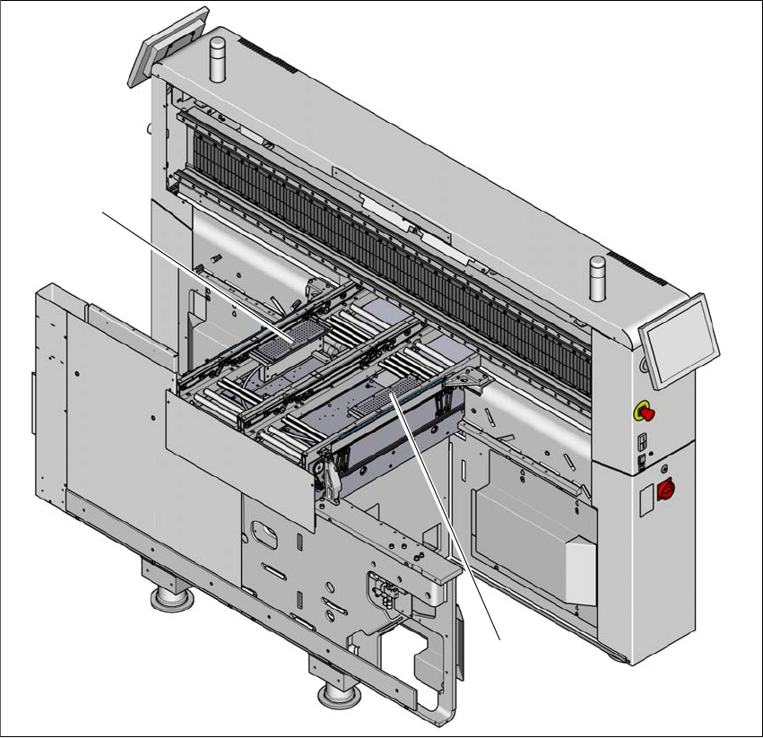
1.4.3 Vacuum Tooling at the SIPLACE TX m
1
Fig. 1.4 - 1 Vacuum Tooling at the SIPLACE TX m - overview
(1) Vacuum tooling at location 1
(2) Vacuum tooling at location 2
(2)
(1)