IPC-CM-770D-1996.pdf - 第135页
January 1996 IPC-CM-770 o O IPc-I-00050 L Figure 25-11 Panel Assembly Tooling Holes IPC-1-00361 L Figure 25-12 Positive Symbol Machine Correction PCB Layout: Spacing Wave Solder -7 un o &%?I IPC-1-00362 Figure 25-13 …
IPC-CM-770
Januaty
1996
are critical to insure that the part body does not “shadow”
the solder joint and, depending on how the component
boards are oriented on a panel, will play a significant role
in the type of solder joint when the boards are to be wave
soldered (see Figure 25-13).
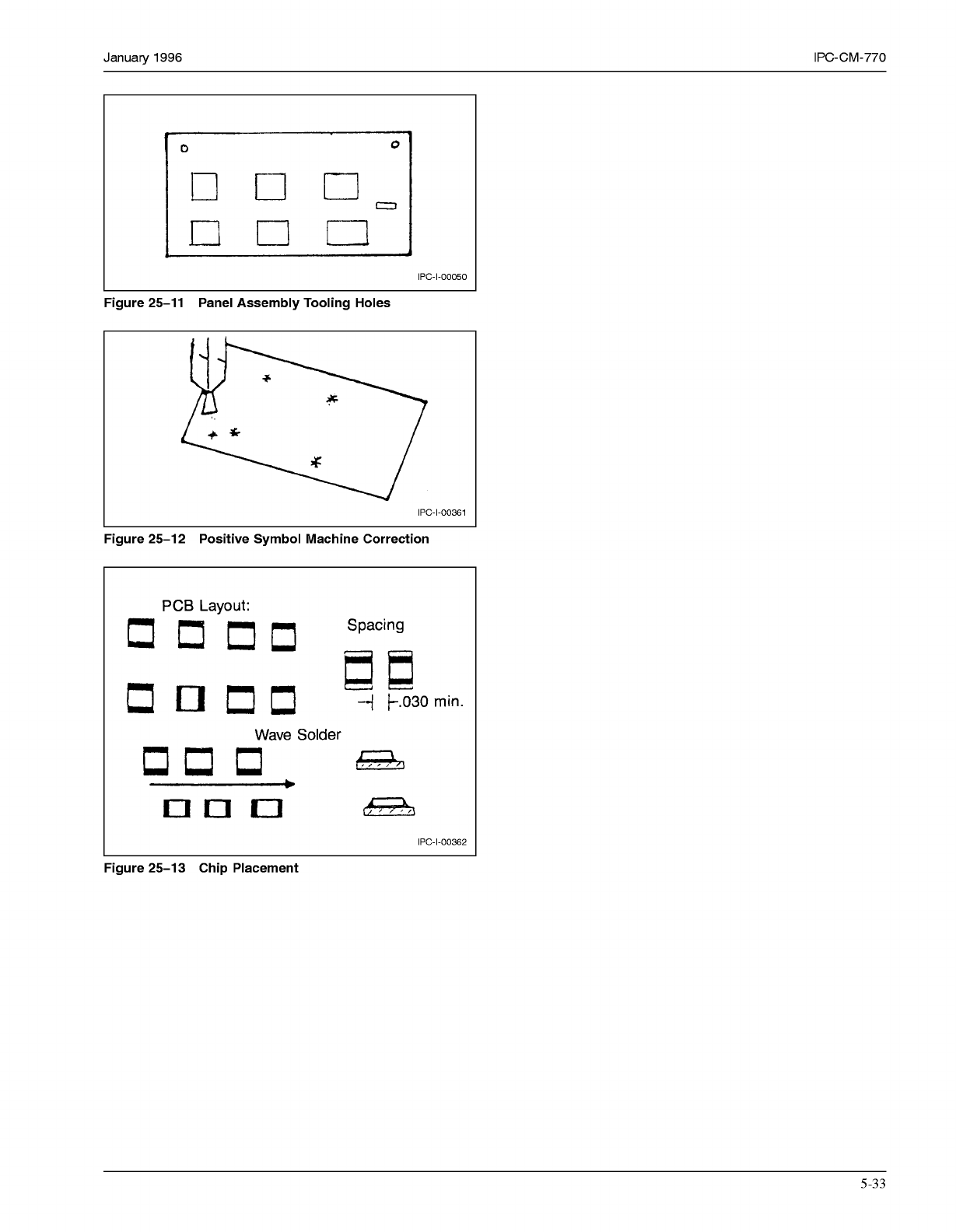
Some assembly equipments use special sensing symbols
which have been incorporated into the design. In this fash-
ion, the equipment senses the location of the symbol and
can zero in on a particular board, or even pattern. Material
movement or shifting of patterns can, therefore, be com-
pensated for by the assembly equipment. With special tool-
ing, features, or holes, the automated assembly can, there-
fore, accommodate panels of
18
to 24 inches without any
loss of accuracy of the component placement task (see Fig-
ure 25-12).
Designs should consider whether the assembly will be
accomplished using board assembly or panel assembly.
This becomes increasingly more important, depending on
the technique used for attachment, in that board to compo-
nent orientation is critical in some instances where the
parts pass through the wave and are, thus, attached to the
land patterns. Placement of parts and orientation of parts
are critical to insure that the part body does not “shadow”
the solder joint and, depending on how the component
boards are oriented on a panel, will play a significant role
in the type of solder joint when the boards are to be wave
soldered (see Figure 25-13).
25.4 Quality Assurance
The quality assurance aspects
are the same for intermixed assemblies as they are on
through-the-board and surface mounted assemblies. There
is however, a greater need for process control in that there
are several sequences of assembly prior to completing the
task.
Inspection levels are instituted to ensure that quality assur-
ance aspects of electronic asemblies are inspected for con-
formance of acceptability criteria of IPC-A-6
10.
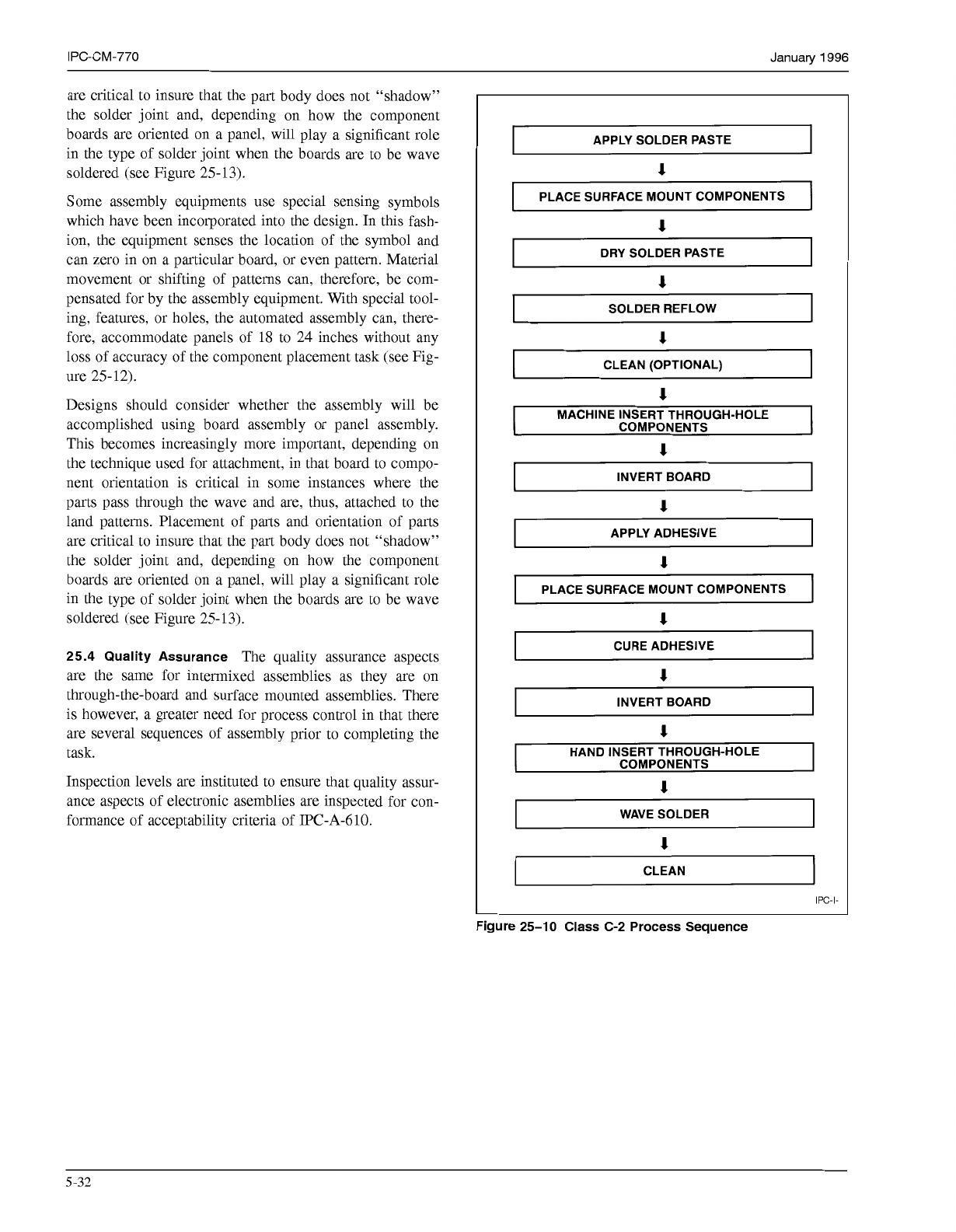
APPLY SOLDER PASTE
1
PLACE SURFACE MOUNT COMPONENTS
1
DRY SOLDER PASTE
1
I
SOLDER REFLOW
I
1
CLEAN (OPTIONAL)
I
MACHINE INSERT THROUGH-HOLE
COMPONENTS
1
INVERT BOARD
APPLY ADHESIVE
1
PLACE SURFACE MOUNT COMPONENTS
1
I
CURE ADHESIVE
1
I
INVERT BOARD
I
1
HAND INSERT THROUGH-HOLE
COMPONENTS
1
WAVE SOLDER
1
CLEAN
IPC-I-
Figure 25-10 Class C-2 Process Sequence
5-32
COPYRIGHT Association Connecting Electronics Industries
Licensed by Information Handling Services
COPYRIGHT Association Connecting Electronics Industries
Licensed by Information Handling Services
January
1996
IPC-CM-770
o
O
IPc-I-00050
L
Figure 25-11 Panel Assembly Tooling Holes
IPC-1-00361
L
Figure 25-12 Positive Symbol Machine Correction
PCB
Layout:
Spacing
Wave Solder
-7
un
o
&%?I
IPC-1-00362
Figure 25-13 Chip Placement
5-33
COPYRIGHT Association Connecting Electronics Industries
Licensed by Information Handling Services
COPYRIGHT Association Connecting Electronics Industries
Licensed by Information Handling Services
IPC-CM-770
Januaty
1996
5-34
COPYRIGHT Association Connecting Electronics Industries
Licensed by Information Handling Services
COPYRIGHT Association Connecting Electronics Industries
Licensed by Information Handling Services