IPC-CM-770D-1996.pdf - 第17页
January 1996 IPC-CM-770 m Components (mounted) on only one side of the board Through-hole Simple I uu uu uu iz o0 e CHIP COMPONENT SOE 'OLDER m COMPONENT PLCC CHIP PASTE DIP DIP .. SMTITH . . . . . . . .. ,, " …
IPC-CM-770
Januaty
1996
which uninterrupted service is desired but is not critical.
Certain cosmetic imperfections are allowed.
CLASS 3 High Reliability Electronic Products
Includes the equipment for commercial and military prod-
ucts where continued performance or performance on
demand is critical. Equipment downtime cannot be toler-
ated, and functionality is required for such applications as
life support items, or missile systems. Printed boards and
printed board assemblies in this class are suitable for appli-
cations where high levels of assurance are required and
service is essential.
The land patterns in this standard have the capability of
accommodating all three performance classifications.
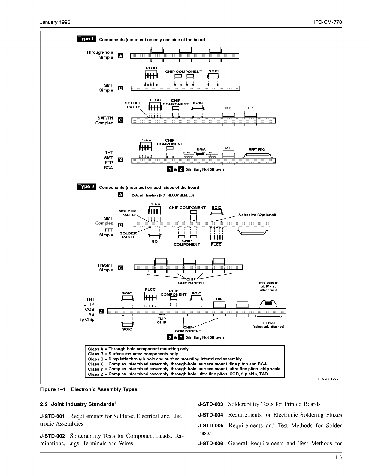
1.4 ASSEMBLY TYPES
A type designation signifies fur-
ther sophistication describing whether components are
mounted on one or both sides of the packaging and inter-
connecting structure. Type
1
defines an assembly that has
components mounted on only one side; type
2
is an assem-
bly with components on both sides. Type
2
is limited to
only class B or C assemblies.
Figure
1-1
shows the relationship of two types of assem-
blies.
The need to apply certain design concepts should depend
on the complexity and precision required to produce a par-
ticular land pattern or printed board structure. Any design
class may be applied to any of the end-product equipment
categories; therefore, a moderate complexity (Type 1B)
would define components mounted on one side (all surface
mounted) and when used in a Class
2
product (dedicated
service electronics) is referred to as type lB, Class
2.
The
product described as Type lB, Class
2
might be used in any
of the end-use applications; the selection of class being
dependent on the requirements of the customers using the
application.
1.5 Presentation
All dimensions and tolerances are
expressed in metric. Reference information is shown in
parentheses
(
).
2.0 REFERENCE DOCUMENTS
The following documents, of the issue currently in effect
form a part of this document to the extent specified herein.
Other documents listed are for reference purposes to assist
the user.
2.1 Institute for Interconnecting and Packaging Elec-
tronic Circuits (IPC)’
IPC-T-50
Terms and Definitions
IPC-SCIO
Post Solder Solvent Cleaning Handbook
IPC-AC-62
Post Solder Aqueous Cleaning Handbook
IPC-RF-245
Performance Specification for Rigid-Flex
Printed Boards
IPC-D-249
Design Standard for Flexible Single- and
Double-Sided Printed Boards
IPC-FC-250
Performance Specification for Single- and
Double-Sided Flexible Printed Wiring
IPC-D-275
Design Standard for Rigid Printed Boards and
Rigid Printed Board Assemblies
IPC-RB-276
Qualification and Performance Specification
for Rigid Printed Boards
IPC-D-322
Guidelines for Selecting Printed Wiring Board
Sizes Using Standard Panel Sizes
IPC-MC-324
Qualification and Performance Specification
for Metal Core Boards
IPC-D-325
Documentation Requirements for Printed
Boards, Assemblies, and Support Drawings
IPC-D-330
Design Guide
IPC-PD-335
Electronic Packaging Handbook
IPC-C-406
Design and Application Guidelines for Surface
Mount Connectors
IPC-A-600
Acceptability of Printed Boards
IPC-A-61
O
Acceptability of Electronic Assemblies
IPC-R-700
Suggested Guidelines for Modification,
Rework, and Repair of Printed Wiring Boards and Assem-
blies
IPC-SM-782
Surface Mount Design and Land Pattern
Standard
IPC-SM-784
Guidelines for Chip-On-Board Technology
Implementation
IPC-AJ-820
Assembly and Joining Handbook
IPC-CA-821
General Requirements for Thermally Con-
ductive Adhesives
IPC-CC-830
Electrical Insulating Compounds for Printed
Board Assemblies
IPC-SM-840
Qualification and Performance of Permanent
Polymer Coating (Solder Mask) for Printed Boards
IPC-H-855
Hybrid Microcircuit Design Guide
SMC-TR-001
An Introduction to Tape Automated Bonding
Find Pitch Technology
l.
Institute for Interconnecting and Packaging Electronic Circuits,
2215
Sanders Road, Northbrook,
IL
60062.
1-2
COPYRIGHT Association Connecting Electronics Industries
Licensed by Information Handling Services
COPYRIGHT Association Connecting Electronics Industries
Licensed by Information Handling Services
January
1996
IPC-CM-770
m
Components (mounted) on only one side of the board
Through-hole
Simple
I
uu
uu
uu
iz
o0
e
CHIP COMPONENT SOE
'OLDER
m
COMPONENT
PLCC CHIP
PASTE DIP DIP
..
SMTITH
. . . . .
. .
..
,,
"
"".
m&A&2
b
:
Complex
i:
II
li
i¡
,
I,
I,
II
u uu u
PLCC
CHID
BGA
&
Similar, Not Shown
m
Components (mounted) on both sides of the board
?-Sided Thru-hole (NOT RECOMMENDED)
SMT
Complex
FPT
Simple
THISMT
1:
i
'4
II
-CHIPe COMPONENT
Wire bond
or
tab IC chip
attachment
PLCC
CHIP
m
COMPONENT
THT
0
m
DIP
COB
Q
I
TAB
Flip Chip
UFTP
..
"".
..
"".
..
II
..
..
D
'"'2
"
"
I
U U
uuu
u u
CHIP
1
/
FLIP
W
"
..
..
-
FPT PKG.
U
SOlC
!CHI/
COMPONENT
&
Similar, Not Shown
(selectively attached)
Class A
=
Through-hole component mounting only
Class B
=
Surface mounted components only
Class C
=
Simplistic through-hole and surface mounting intermixed assembly
Class
X
=
Complex intermixed assembly, through-hole, surface mount, fine pitch and BGA
Class
Y
=
Complex intermixed assembly, through-hole, surface mount, ultra fine pitch, chip scale
Class
2
=
Complex intermixed assembly, through-hole, ultra fine pitch, COB, flip chip, TAB
IPC-1-001229
Figure 1-1 Electronic Assembly Types
2.2 Joint Industry Standards' J-STD-003
Solderability Tests for Printed Boards
J-STD-001
Requirements for Soldered Electrical and Elec-
J-STD-004
Requirements for Electronic Soldering Fluxes
tronic Assemblies
J-STD-005
Requirements and Test Methods for Solder
J-STD-002
Solderability Tests for Component Leads, Ter-
minations, Lugs, Terminals and Wires
J-STD-006
General Requirements and Test Methods for
Paste
1-3
COPYRIGHT Association Connecting Electronics Industries
Licensed by Information Handling Services
COPYRIGHT Association Connecting Electronics Industries
Licensed by Information Handling Services
IPC-CM-770
Januaty
1996
Electronic Grade, Soft Solder Alloys and Fluxed and Non-
Fluxed Solid Solders for Electronic Soldering Applications
2.3 Department of Defense2
MIL-STD-1
O0
Engineering Drawing Practices
MIL-STD-129
Marking for Shipment and Storage
MIL-STD-202
Test Methods for Electronic and Electrical
Component Parts
MIL-STD-454
Standard General Requirements for Elec-
tronic Equipment
MIL-STD-883
Test Methods and Procedures for Microelec-
tronics
MIL-STD-1344
Test Methods for Electrical Connectors
MIL-1-7444
Insulation Sleeving, Electrical, Flexible
MIL-C-11268
Parts, Materials, and Processes, Used in
Electronic Equipment
MIL-P-13949
Plastic Sheet, Laminated, Metal Clad, for
Printed Wiring Boards
MIL-S-1 9500
Semiconductor Devices, General Specifica-
tion
MIL-1-23053
Insulation Sleeving, Electrical, Heat Shrink-
able
MIL-P-28809
Printed Wiring Assemblies
MIL-M-3851
O
Semiconductor Devices, General Specifica-
tion
MIL-P-55110
Printed Wiring Boards
MIL-S-83502
Sockets, Plug-In Electronic Component,
Round Style
2.4 Electronic Industries Association3
JEDEC-95
JEDEC Registered and Standard Outlines for
Solid State Products
RS-167
Type Designation for Receiver Type Tube Sockets
RS-186-9E
Standard Test Methods for Passive Electronic
Component Parts-Method
9,
Solderability Rev. E
RS-192
Holder Outlines and Pin Connections for Quartz
Crystal Units
RS-198
Ceramic Dielectric Capacitors
RS-228
Fixed Electrolytic Tantalum Capacitors
RS-296
Lead Taping, Axial Components
RS-367
Dimensional and Electrical Characteristics Defin-
ing Receiver Type Sockets
RS-376
Fixed Film Dielectric Capacitors in Metallic and
Non-Metallic Cases for D.C. Application
RS-415
Dimensional and Electrical Characteristic Defin-
ing Dual-In-Line-Type Sockets
RS-428
Type Designation System for Microelectronic
Devices
RS-468
Lead Taping, Radial Components
RS-471
Symbol and Label for Electrostatic Sensitive
Devices
RS-481
Lead Taping, Leadless Components
RS-488
Sockets, Individual Lead Types (for Electrical and
Electronic Components)
2.5 American National Standards Institute4
ANSI Y-1 4.5
Dimensioning and Tolerancing
2.6 Underwriters Laboratories5
UL-1244
Electrical and Electronic Measuring and Testing
Equipment
2.7 American Society for Testing and Materials6
B25
Standard Nominal Diameters and Cross-Sectional
Areas of AWG Sizes of Solid Round Wires Used as Elec-
trical Conductors
F72
Gold Wire for Semiconductor Lead Bonding
F487
Fine Aluminum-
1
%
Silicon Wire for Semiconductor
Lead Bonding
D3295
Standard for PTFE Tubing
2.8 Other Documents
IEC-348
Safety Requirements for Electronic Measuring
Apparatus
FCC
Docket
20780
3.0 TERMS AND DEFINITIONS
Terms and definitions used herein are in accordance with
IPC-T-50 except as otherwise specified. Note: Any defini-
tion denoted with as asterisk
(*)
is a reprint of the defini-
tion defined in IPC-T-50.
2. Publications are available from Naval Publications and Form Center, 5801 Tabor Road, Philadelphia, PA 19120.
3. Electronic Industries Association, 2001
"I"
Street, NW, Washington, DC 20006.
4. American National Standards Institute, 11 W. 42nd St., New York, NY 10036.
5. Underwriters Laboratories, Inc., 333 Pfingsten Rd., Northbrook, IL 60062.
6. American Society for Testing and Materials, 1916 Race St., Philadelphia, PA 19103-1187.
1-4
COPYRIGHT Association Connecting Electronics Industries
Licensed by Information Handling Services
COPYRIGHT Association Connecting Electronics Industries
Licensed by Information Handling Services