IPC-CM-770D-1996.pdf - 第99页
January 1996 IPC-CM-770 Table 19-1 Packaging and Interconnecting Structure Comparison ORGANIC BASE SUBSTRATE Epoxy Fiberglass Polyimide Fiberglass Epoxy Aramid Fiber Polyimide Aramid Fiber Polyimide Quartz (Fused Silica)…
IPC-CM-770
Januaty
1996
19.1.3 Metal-Core Boards
Metal core boards or special
printed board constructions are detailed in IPC-D-275.
These types of products, due to their mechanical rigidity,
make the component mounting task somewhat easier. How-
ever, the thermal characteristics of the interconnection
structure require that the soldering or attachment technique
consider the impact that the thermal mass has on the solder
joint solidification.
19.2 Surface Mounting
Surface mounting techniques are
applicable to any type of board or substrate material. How-
ever, when using leadless components, the differing coeffi-
cients of expansion between the component and the sub-
strate must be considered.
Surface mounting is suitable for single sided, double sided
(with or without plated-through-holes), and multilayer
boards. Mounting techniques are independent of board
type.
Techniques which have been developed to minimize the
thermal expansion problem have included the development
of special board types with controlled expansion coeffi-
cients. These include ceramic boards, conventional epoxy-
glass and polyimide- glass boards, and special laminates
such as invar or copper substrate clad with epoxy-glass on
each side. Proper selection of material types and thick-
nesses permits tailoring the thermal expansion coefficients
to any desired value.
Table 19-1 provides a comparison of the advantages and
disadvantages of many of the available printed board
structures.
19.3 Supporting-Plane Printed Board Structures
sup-
porting metallic or non-metallic planes can be used with
conventional printed boards or with customer processing to
enhance printed board properties. Depending on the results
desired, the supporting plane can be electrically functional
or not and can also serve as a structure stiffener, heatsink
and/or CTE constraint.
I
n
I
Circuil
panern
Chip
carrier
I I
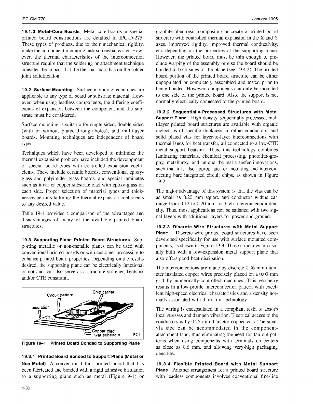
Figure 19-1 Printed Board Bonded to Supporting Plane
19.3.1 Printed Board Bonded to Support Plane (Metal or
Non-Metal)
A conventional thin printed board that has
been fabricated and bonded with a rigid adhesive insulation
to a supporting plane such as metal (Figure 9-1) or
graphite-fiber resin composite can create a printed board
structure with controlled thermal expansion in the
X
and
Y
axes, improved rigidity, improved thermal conductivity,
etc. depending on the properties of the supporting plane.
However, the printed board must be thin enough to pre-
clude warping of the assembly or else the board should be
bonded to both sides of the plane (see 19.4.2). The printed
board portion of the printed board structure can be either
unpopulated or completely assembled and tested prior to
being bonded. However, components can only be mounted
to one side of the printed board. Also, the support is not
normally electrically connected to the printed board.
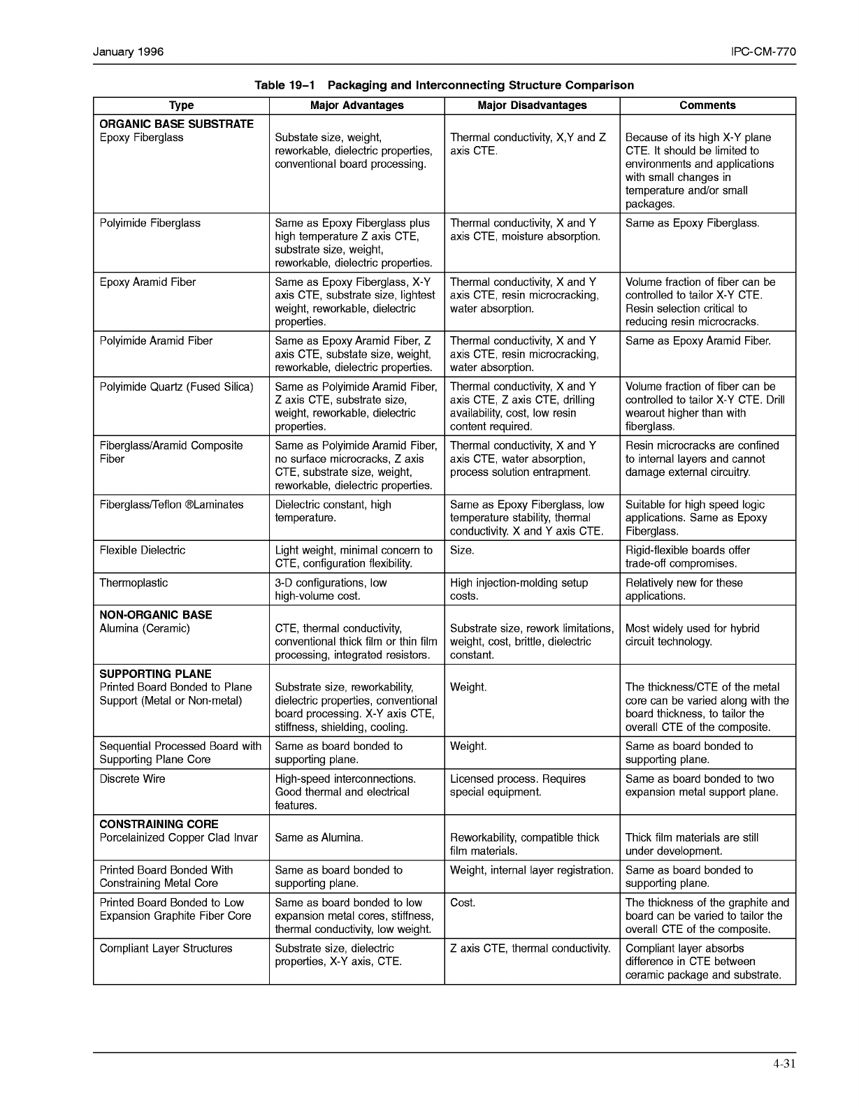
19.3.2 Sequentially-Processed Structures with Metal
Support Plane
High-density, sequentially processed, mul-
tilayer printed board structures are available with organic
dielectrics of specific thickness, ultrafine conductors, and
solid plated vias for layer-to-layer interconnections with
thermal lands for heat transfer, all connected to a low-CTE
metal support heatsink. Thus, this technology combines
laminating materials, chemical processing, photolithogra-
phy, metallurgy, and unique thermal transfer innovations,
such that it is also appropriate for mounting and intercon-
necting bare integrated circuit chips, as shown in Figure
19-2.
The major advantage of this system is that the vias can be
as small as 0.20 mm square and conductor widths can
range from 0.12 to 0.20 mm for high interconnection den-
sity. Thus, most applications can be satisfied with two sig-
nal layers with additional layers for power and ground.
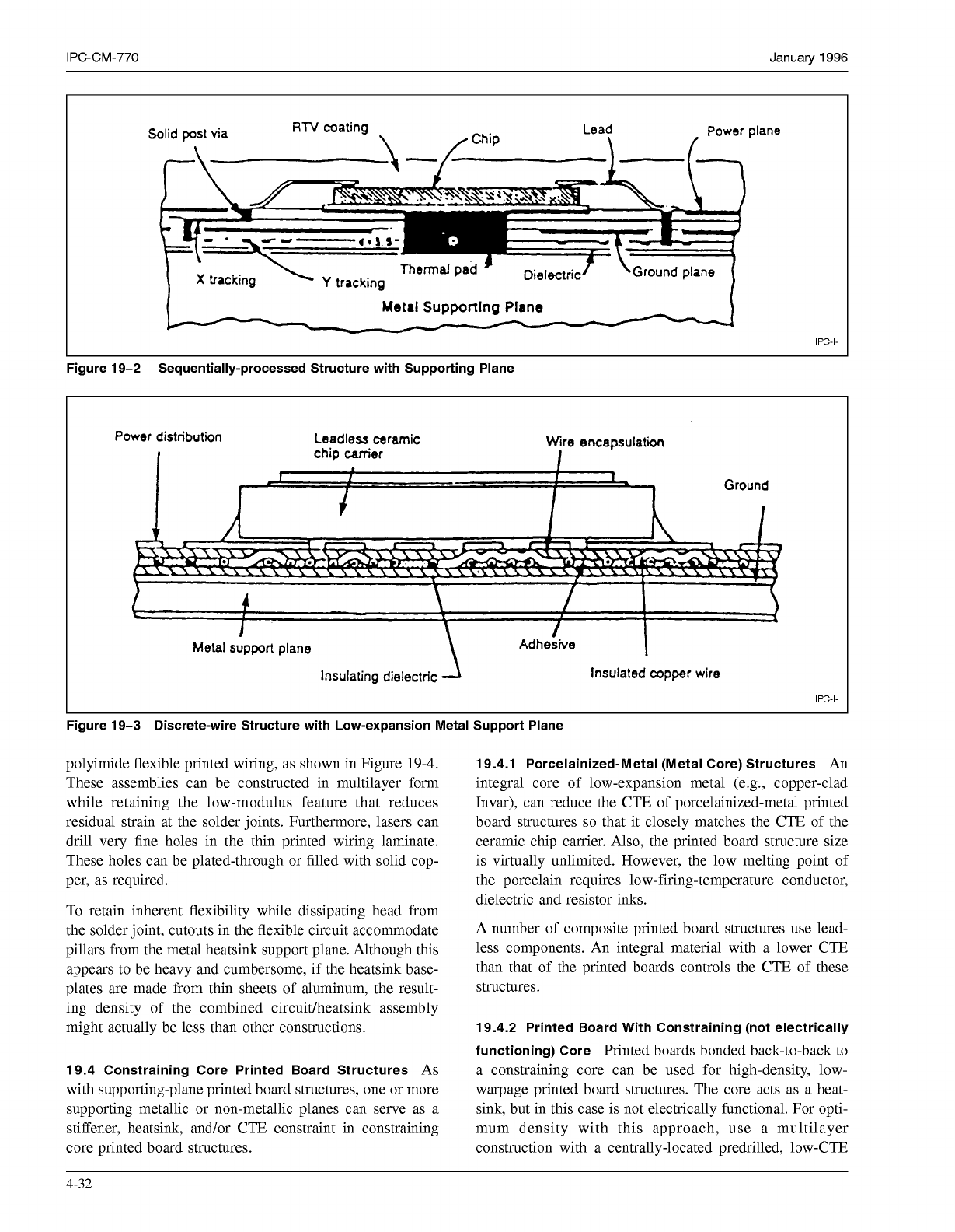
19.3.3 Discrete-Wire Structures with Metal Support
Plane.
Discrete-wire printed board structures have been
developed specifically for use with surface mounted com-
ponents, as shown in Figure 19-3. These structures are usu-
ally built with a low-expansion metal support plane that
also offers good heat dissipation.
The interconnections are made by discrete
0.06
mm diam-
eter insulated copper wires precisely placed on a 0.03 mm
grid by numerically-controlled machines. This geometry
results in a low-profile interconnection pattern with excel-
lent high-speed electrical characteristics and a density nor-
mally associated with thick-film technology.
The wiring is encapsulated in a compliant resin to absorb
local stresses and dampen vibration. Electrical access to the
conductors is by 0.25 mm diameter copper vias. The small
via size can be accommodated in the component-
attachment land, thus eliminating the need for fan-out pat-
terns when using components with terminals on centers
as close as
0.6
mm, and allowing very-high packaging
densities.
19.3.4 Flexible Printed Board with Metal Support
Plane
Another arrangement for a printed board structure
with leadless components involves conventional fine-line
4-30
COPYRIGHT Association Connecting Electronics Industries
Licensed by Information Handling Services
COPYRIGHT Association Connecting Electronics Industries
Licensed by Information Handling Services
January
1996
IPC-CM-770
Table
19-1
Packaging and Interconnecting Structure Comparison
ORGANIC BASE SUBSTRATE
Epoxy Fiberglass
Polyimide Fiberglass
Epoxy Aramid Fiber
Polyimide Aramid Fiber
Polyimide Quartz (Fused Silica)
Fiberglass/Aramid Composite
Fiber
Fiberglass/Teflon @Laminates
Flexible Dielectric
Thermoplastic
NON-ORGANIC BASE
Alumina (Ceramic)
SUPPORTING PLANE
Printed Board Bonded to Plane
Support (Metal or Non-metal)
Sequential Processed Board with
Supporting Plane Core
Discrete Wire
CONSTRAINING CORE
Porcelainized Copper Clad Invar
Printed Board Bonded With
Constraining Metal Core
Printed Board Bonded to Low
Expansion Graphite Fiber Core
Compliant Layer Structures
Major Advantages
Substate size, weight,
reworkable, dielectric properties,
conventional board processing.
Same as Epoxy Fiberglass plus
high temperature
Z
axis CTE,
substrate size, weight,
reworkable, dielectric properties.
Same as Epoxy Fiberglass, X-Y
axis CTE, substrate size, lightest
weight, reworkable, dielectric
properties.
Same as Epoxy Aramid Fiber,
Z
axis CTE, substate size, weight,
reworkable, dielectric properties.
Same as Polyimide Aramid Fiber,
Z
axis CTE, substrate size,
weight, reworkable, dielectric
properties.
Same as Polyimide Aramid Fiber,
no surface microcracks,
Z
axis
CTE, substrate size, weight,
reworkable, dielectric properties.
Dielectric constant, high
temperature.
Light weight, minimal concern to
CTE, configuration flexibility.
3-D configurations, low
high-volume cost.
CTE, thermal conductivity,
conventional thick film or thin film
processing, integrated resistors.
Substrate size, reworkability,
dielectric properties, conventional
board processing. X-Y axis CTE,
stiffness, shielding, cooling.
Same as board bonded to
supporting plane.
High-speed interconnections.
Good thermal and electrical
features.
Same as Alumina.
Same as board bonded to
supporting plane.
Same as board bonded to low
expansion metal cores, stiffness,
thermal conductivity, low weight.
Substrate size, dielectric
properties, X-Y axis, CTE.
Major Disadvantages
Because of its high X-Y plane Thermal conductivity, X,Y and
Z
Comments
axis CTE. CTE. It should be limited to
environments and applications
with small changes in
temperature and/or small
packages.
Thermal conductivity, X and Y
axis CTE, moisture absorption.
Same as Epoxy Fiberglass.
Thermal conductivity, X and Y
Resin selection critical to water absorption.
controlled to tailor X-Y CTE. axis CTE, resin microcracking,
Volume fraction of fiber can be
reducing resin microcracks.
Thermal conductivity, X and Y Same as Epoxy Aramid Fiber.
axis CTE, resin microcracking,
water absorption.
Thermal conductivity, X and Y Volume fraction of fiber can be
axis CTE,
Z
axis CTE, drilling controlled to tailor X-Y CTE. Drill
availability, cost, low resin wearout higher than with
content required.
fiberglass.
Thermal conductivity, X and Y Resin microcracks are confined
axis CTE, water absorption, to internal layers and cannot
process solution entrapment.
damage external circuitry.
Same as Epoxy Fiberglass, low Suitable for high speed logic
temperature stability, thermal applications. Same as Epoxy
conductivity. X and Y axis CTE.
Fiberglass.
Size. Rigid-flexible boards offer
High injection-molding setup Relatively new for these
trade-off compromises.
costs.
applications.
Substrate size, rework limitations,
circuit technology. weight, cost, brittle, dielectric
Most widely used for hybrid
constant.
Weight.
The thickness/CTE of the metal
core can be varied along with the
board thickness, to tailor the
overall CTE of the composite.
supporting plane.
Weight.
expansion metal support plane. special equipment.
Same as board bonded to two
Licensed process. Requires
Same as board bonded to
Reworkability, compatible thick
Same as board bonded to Weight, internal layer registration.
under development. film materials.
Thick film materials are still
supporting plane.
board can be varied to tailor the
overall CTE of the composite.
difference in CTE between
ceramic package and substrate.
Cost. The thickness of the graphite and
Z
axis CTE, thermal conductivity. Compliant layer absorbs
4-3
1
COPYRIGHT Association Connecting Electronics Industries
Licensed by Information Handling Services
COPYRIGHT Association Connecting Electronics Industries
Licensed by Information Handling Services
IPC-CM-770
Januaty
1996
Power
plane
Metal
Supporting Plane
IPC-I-
Figure 19-2 Sequentially-processed Structure with Supporting Plane
Power
distribution
Leadless
ceramic
Wire
encapsulation
Metal support plane
Insulating dielectric Insulated copper wire
IPC-I-
Figure 19-3 Discrete-wire Structure with Low-expansion Metal Support Plane
polyimide flexible printed wiring, as shown in Figure
19-4.
These assemblies can be constructed in multilayer form
while retaining the low-modulus feature that reduces
residual strain at the solder joints. Furthermore, lasers can
drill very fine holes in the thin printed wiring laminate.
These holes can be plated-through or filled with solid cop-
per, as required.
To retain inherent flexibility while dissipating head from
the solder joint, cutouts in the flexible circuit accommodate
pillars from the metal heatsink support plane. Although this
appears to be heavy and cumbersome, if the heatsink base-
plates are made from thin sheets of aluminum, the result-
ing density of the combined circuidheatsink assembly
might actually be less than other constructions.
19.4 Constraining Core Printed Board Structures
As
with supporting-plane printed board structures, one or more
supporting metallic or non-metallic planes can serve as a
stiffener, heatsink, and/or CTE constraint in constraining
core printed board structures.
19.4.1 Porcelainized-Metal (Metal Core) Structures
An
integral core of low-expansion metal (e.g., copper-clad
Invar), can reduce the CTE of porcelainized-metal printed
board structures
so
that it closely matches the CTE of the
ceramic chip carrier. Also, the printed board structure size
is virtually unlimited. However, the low melting point of
the porcelain requires low-firing-temperature conductor,
dielectric and resistor inks.
A number of composite printed board structures use lead-
less components. An integral material with a lower CTE
than that of the printed boards controls the CTE of these
structures.
19.4.2 Printed Board With Constraining (not electrically
functioning) Core
Printed boards bonded back-to-back to
a constraining core can be used for high-density, low-
warpage printed board structures. The core acts as a heat-
sink, but in this case is not electrically functional. For opti-
mum density with this approach, use a multilayer
construction with a centrally-located predrilled, low-CTE
4-32
COPYRIGHT Association Connecting Electronics Industries
Licensed by Information Handling Services
COPYRIGHT Association Connecting Electronics Industries
Licensed by Information Handling Services