IPC-CM-770D-1996.pdf - 第142页
IPC-CM-770 Januaty 1996 Use conduclive or anti. bags and contamers n Usa wrist straps and I z Avord lead handimg // / Pick up static sensitive devices only by the body. Keep Discharge personal static before handling devi…
January
1996
IPC-CM-770
OETAIL
"A"
#14
gauge, black insulated
Gound
Wire
Terminal
10
Candull
1
0
808
Block
See
Oatall
"A"
1
-
To
Mat
To
firth
-
Ground
14
gauge, black insulat
nccrconnccling
Wire
rom
TOP
(0
Mal
FLOOR
MAT
(or
conductive
floo
IPC-1-00299
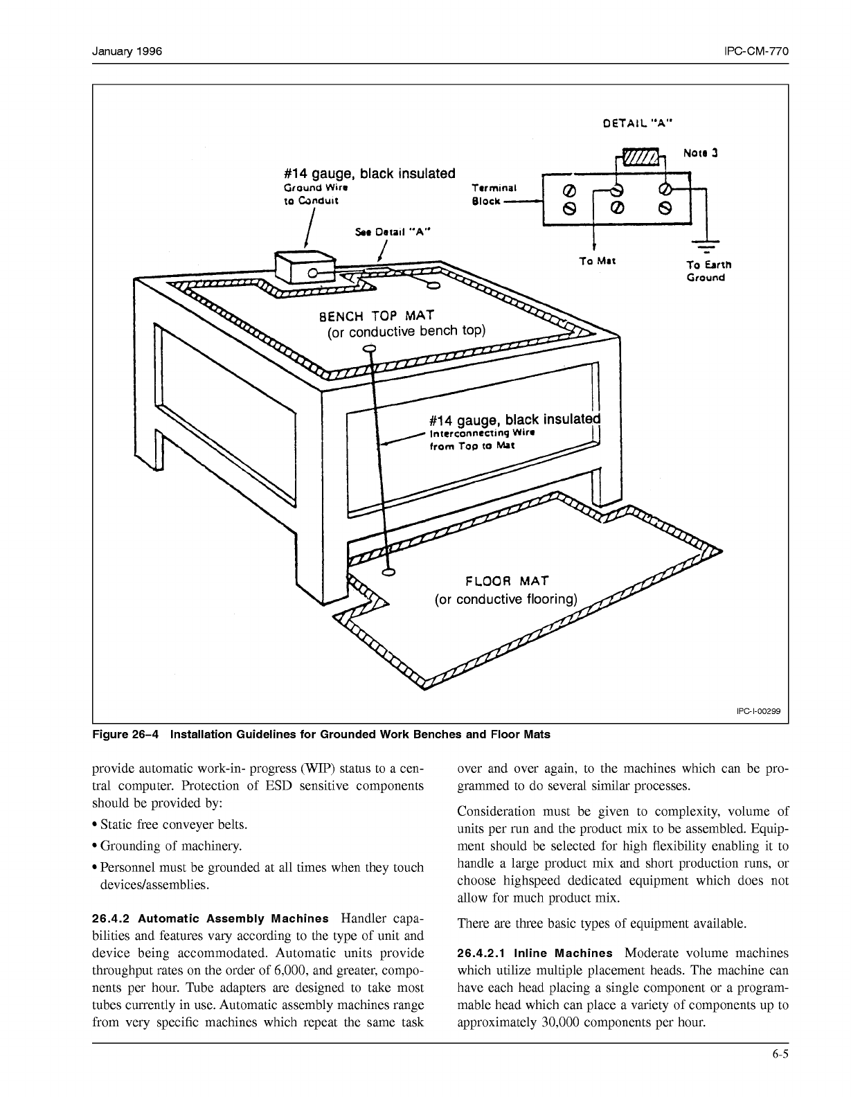
Figure 26-4 Installation Guidelines for Grounded Work Benches and Floor Mats
provide automatic work-in- progress (WIP) status to a cen-
tral computer. Protection of ESD sensitive components
should be provided by:
Static free conveyer belts.
Grounding of machinery.
Personnel must be grounded at all times when they touch
devicedassemblies.
26.4.2 Automatic Assembly Machines
Handler capa-
bilities and features vary according to the type of unit and
device being accommodated. Automatic units provide
throughput rates on the order of
6,000,
and greater, compo-
nents per hour. Tube adapters are designed to take most
tubes currently in use. Automatic assembly machines range
from very specific machines which repeat the same task
over and over again, to the machines which can be pro-
grammed to do several similar processes.
Consideration must be given to complexity, volume of
units per run and the product mix to be assembled. Equip-
ment should be selected for high flexibility enabling it to
handle a large product mix and short production runs, or
choose highspeed dedicated equipment which does not
allow for much product mix.
There are three basic types of equipment available.
26.4.2.1 lnline Machines
Moderate volume machines
which utilize multiple placement heads. The machine can
have each head placing a single component or a program-
mable head which can place a variety of components up to
approximately
30,000
components per hour.
6-5
COPYRIGHT Association Connecting Electronics Industries
Licensed by Information Handling Services
COPYRIGHT Association Connecting Electronics Industries
Licensed by Information Handling Services
IPC-CM-770
Januaty
1996
Use
conduclive or anti.
bags and contamers
n
Usa
wrist
straps
and
I
z
Avord lead handimg
//
/
Pick
up
static
sensitive
devices
only by the
body.
Keep
Discharge personal static before
handling devices.
-
.
//
í2<
I
handling
work
stauon cmap
"
Avoid all plastic, vinyl and Styrofoam in the
work
area, except
anti-static
or
conductwe plastics.
Assemate
only
at gmundecl
work
s~atron
AVOIO
Charge generalron
Do
not
subject semconductors
to
shdlng movements over
any surface at any time.
IPC-I-O0301
Figure
26-5
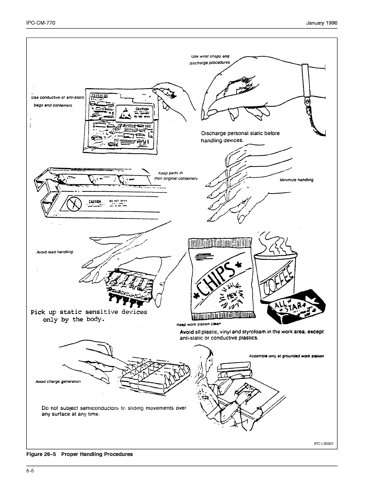
Proper Handling Procedures
6-6
COPYRIGHT Association Connecting Electronics Industries
Licensed by Information Handling Services
COPYRIGHT Association Connecting Electronics Industries
Licensed by Information Handling Services
January
1996
IPC-CM-770
26.4.2.2 Sequential Machines
Provides for flexibility of
programming placement of components-2,000 to 12,000
per hour. This level of automation allows for some compo-
nent testing prior to the placement the board.
26.4.2.3 Mass Placement Machines
Very high volume,
fairly dedicated machine used in the matrix of stocks or
multiplicity of tapes, which assembles a total circuit with
one or more codes of the machine, up to 200,000 compo-
nents per hour.
27.0 SOLDER-RELATED CONSIDERATIONS
This section details the printed wiring board, component,
surface finish, solderability, materials and various solder
process methodologies which can affect a manufacturer’s
soldering process yields.
27.1 General Considerations
The component mounting
technique used, the mounting sequence followed, and the
resultant assembly configuration will impact the soldering
techniques which can be applied for interconnection of
components and printed boards as well as the resultant
quality of the solder joints.
Excessively large clearances can result in draining of the
solder. Lead extension through the hole must be adequate
to ensure opportunity for a good solder joint and subse-
quent inspection but not
so
long as to cause interference
with tooling for subsequent processes or shorting to adja-
cent runs or assemblies.
Component and board considerations, independent of type,
that impact soldering should be considered.
27.1.1 Part Type
Mass soldering of assemblies is usually
done with either a solder wave or a reflow process with hot
air, radiation (infrared), condensation heat transfer or con-
ductive plate. Many leaded devices such as chip carriers
are currently not considered appropriate for wave soldering
and must be soldered with the reflow process. These
devices may appear on either the “solder source” or the
“solder destination” side of the board. All surface mounted
components mounted on the “solder destination” side must
be reflow soldered. Surface mounted devices with fewer
leads such as resistors, capacitors and small outline
(SO)
devices can be assembled with solder waves but the orien-
tation of the parts becomes important. Passive chips, SOTS,
SOICs and other components that can tolerate immersion
in the molten solder of a wave soldering machine may be
mounted on the “solder source” side of printed wiring
assemblies.
Through-hole mounted parts have the potential of resultant
lower quality solder joints if insulation material, potting
compound or other material is allowed to protrude into the
hole. Another characteristic of these devices is the ten-
dency to “raise” during the fluxinglwave soldering process
if not clinched or mechanically retained. For wave solder-
ing the through hole mounted devices should be mounted
on the “solder destination” side of the board. These
devices may not be compatible with reflow processes. The
component mass is another factor to be reviewed. Heavy
mass components require longer soldering times due to
their heatsinking characteristics.
27.1.2 LeadlLand Relationships
The leadless and
leaded termination provide different solder joint geometries
and the stress distribution is different in each case. If leads
are too short to protrude through the printed wiring board
or if the surface mount lands are too small, soldering may
become difficult. Printed board hole diameters must be con-
sidered for the type product to be used.
Costs and problems can be reduced if the designer selects
his devices prior to printed board design and then designs
the proper hole or land size, etc. “Non-standard’’ holes
and land patterns increase costs by making “non-
standard” devices mandatory.
Proper spacings can greatly increase automatic, semi-
automatic and manual speed of component placement.
Features should be, if possible, in straight line patterns
rather than random and they should be placed in such a
fashion that it will not be necessary to readjust the board
to the product.
Tooling holes should be placed as far apart as possible.
The designer must be certain no pre-mounted components
will interfere with the proper machine installation of
those devices that will subsequently be installed.
Printed board holes may be “non” plated or “through”
plated, drilled or punched, dependent upon the device
which will be eventually used and the quality required in
the final printed board. As a general rule, a drilled hole
will be more consistent in size and is advised where a
hole will eventually be plated through. Punched holes in
multilayer printed boards are not recommended since the
internal conductors may be damaged.
27.1.2.1 Leadless Component Terminations
This
geometry provides no compliancy, it results in a very rigid,
small lap solder joint depending on the reflowed solder
material system providing desired mechanical properties.
Visual inspection of the joint is limited to fillet appearance
on any castellation and pad extension. Cleaning is more
difficult with this geometry than with the leaded
termination.
27.1.2.2 Leaded Component Termination
This geom-
etry results in a narrow solder fillet. It provides compliancy
which can compensate for some degree of mismatch in
expansion between the component package and the sub-
strate. Visual inspection of solder joints is somewhat easier
6-7
COPYRIGHT Association Connecting Electronics Industries
Licensed by Information Handling Services
COPYRIGHT Association Connecting Electronics Industries
Licensed by Information Handling Services