IPC-CM-770D-1996.pdf - 第156页
IPC-CM-770 Januaty 1996 Conformal coating should completely cover the surfaces of the assembly, including soldered joints, wires, and compo- nents, other than those areas and components deliberately masked. Typical thick…
January
1996
IPC-CM-770
The cleanliness tests of
J-STD-001
should be used to vali-
date the cleaning process chosen and should be performed
at a frequency that ensures compliance.
29.0 CONFORMAL COATING-RELATED
CONSIDERATIONS
A conformal coating is a thin layer of insulating material
which is applied to a printed board assembly. This material
follows closely the contours of the board and components.
It “conforms” to the shape of the assembly, and ideally
will produce a film of consistent thickness over the entire
assembled printed board. Assembled printed boards are fre-
quently given a conformal coating to assist them in func-
tioning under certain environmental conditions.
29.1 General Considerations
Correctly chosen, and
carefully applied, conformal coating will help to protect the
assembly from the following hazards:
Humidity
Dust and dirt
Airborne contaminants-.g., smoke, chemical vapors
Conducting particles-.g., metal chip, filing
Accidental short circuit by dropped tools, fasteners, etc.
Abrasion damage
Vibration and shock (to a certain extent)
Conformal coating is not a substitute for good design, or
the selection of adequate components and materials. It
does, however, assist the designer in producing equipment
which will live under hostile conditions. The conformal
coating should be compatible with any soldermask used on
the assembly. Conformal coatings protect the electrical
characteristics of the assembly by doing the following:
Preventing contamination of the dielectric surface by field
soil, which in humid environments can cause electrical
leakage.
Inhibiting the growth of fungus, thereby protecting the
electrical characteristics. Even non-nutrient surfaces can
support fungus growth when contaminated with field soils
such as oil vapor.
Suppressing electrical flashover between conductors at
high altitudes.
The secondary function of conformal coating is to help
support the components
so
that the entire mass of the com-
ponent is not carried by the solder joints.
Properties to be considered in quality test and/or
evaluations:
Appearance
Thickness
Fungus resistance
Adhesion
Shelf life
Pot life
Abrasion resistance
Solvent resistance
Flammability
Dielectric withstanding voltage
Moisture resistance
Thermal shock resistance
Thermal humidity aging
Fluorescence
Resonance
For additional information on conformal coating see IPC-
CC-830.
29.1.1 Selection Criteria
Conformal coating resins are
selected to fulfill the above requirements listed for adhe-
sives and protective coatings plus several other minor ones
such as transparency (to permit reading component values
after coating) and flexibility (to prevent damage to compo-
nents in temperature cycling). However, certain limitations
are inherent in conformal coatings:
Since they are permeable to water vapor and are not for-
mulated with corrosion inhibitors such as chromates, they
will not prevent corrosion caused by active electrolytic
salts on the part being coated or salts trapped under the
coating on the surface of the part.
Since they are permeable to water, their insulation resis-
tance decreases as the thickness of the film increases,
particularly in a fillet of resin around a component (such
as in integrated circuit).
Since coatings are organic and fill the voids between con-
ductors, they cause a marked change in interlead capaci-
tance.
Coatings have a high coefficient of thermal expansion,
so
they can exert a lifting force certain components, causing
solder joint on failure.
Coatings do not exhibit exceptional adhesion to metals,
particularly solder.
Paraxylylene coatings excepted, most conformal coating
resins are similar to organic finishes and will exhibit pin-
holing and thin spots on sharp points, edges of parts and
conductor edges.
The above limitations can be overcome through careful
design of the assemblies and care in the application
processes.
29.2 Materials
The conformal coating should be suffi-
ciently flexible to permit bending without cracking or craz-
ing at design temperatures.
6-19
COPYRIGHT Association Connecting Electronics Industries
Licensed by Information Handling Services
COPYRIGHT Association Connecting Electronics Industries
Licensed by Information Handling Services
IPC-CM-770 Januaty 1996
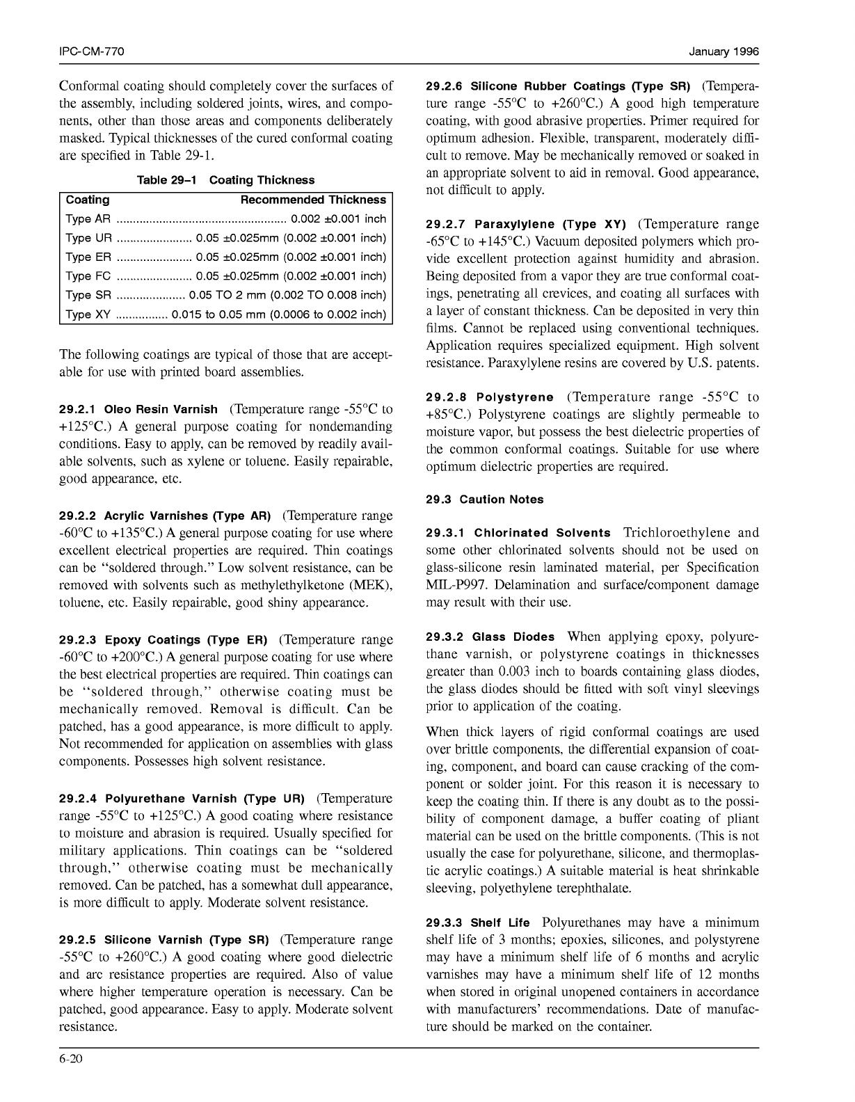
Conformal coating should completely cover the surfaces
of
the assembly, including soldered joints, wires, and compo-
nents, other than those areas and components deliberately
masked. Typical thicknesses of the cured conformal coating
are specified in Table 29-1.
Table 29-1 Coating Thickness
Coating Recommended Thickness
Type
AR
....................................................
0.002 +0.001 inch
Type
UR .......................
0.05 +0.025mm (0.002 +0.001 inch)
Type
ER
.......................
0.05 +0.025mm (0.002 +0.001 inch)
Type FC
.......................
0.05 +0.025mm (0.002 +0.001 inch)
Type
SR .....................
0.05 TO 2 mm (0.002 TO
0.008
inch)
Type
XY
................
0.015
to
0.05 mm (0.0006
to
0.002 inch)
The following coatings are typical of those that are accept-
able for use with printed board assemblies.
29.2.1 Oleo Resin Varnish
(Temperature range -55°C to
+125”C.) A general purpose coating for nondemanding
conditions. Easy to apply, can be removed by readily avail-
able solvents, such as xylene or toluene. Easily repairable,
good appearance, etc.
29.2.2 Acrylic Varnishes (Type AR)
(Temperature range
-60°C to +135”C.) A general purpose coating for use where
excellent electrical properties are required. Thin coatings
can be “soldered through.” Low solvent resistance, can be
removed with solvents such as methylethylketone (MEK),
toluene, etc. Easily repairable, good shiny appearance.
29.2.3 Epoxy Coatings (Type ER)
(Temperature range
-60°C to +200”C.) A general purpose coating for use where
the best electrical properties are required. Thin coatings can
be “soldered through,” otherwise coating must be
mechanically removed. Removal is difficult. Can be
patched, has a good appearance, is more difficult to apply.
Not recommended for application on assemblies with glass
components. Possesses high solvent resistance.
29.2.4 Polyurethane Varnish (Type
UR)
(Temperature
range -55°C to +125”C.) A good coating where resistance
to moisture and abrasion is required. Usually specified for
military applications. Thin coatings can be “soldered
through,” otherwise coating must be mechanically
removed. Can be patched, has a somewhat dull appearance,
is more difficult to apply. Moderate solvent resistance.
29.2.5 Silicone Varnish (Type
SR)
(Temperature range
-55°C to +260”C.) A good coating where good dielectric
and arc resistance properties are required. Also of value
where higher temperature operation is necessary. Can be
patched, good appearance. Easy to apply. Moderate solvent
resistance.
29.2.6 Silicone Rubber Coatings (Type
SR)
(Tempera-
ture range -55°C to +260”C.) A good high temperature
coating, with good abrasive properties. Primer required for
optimum adhesion. Flexible, transparent, moderately diffi-
cult to remove. May be mechanically removed or soaked in
an appropriate solvent to aid in removal. Good appearance,
not difficult to apply.
29.2.7 Paraxylylene (Type
XY)
(Temperature range
-65°C to +145”C.) Vacuum deposited polymers which pro-
vide excellent protection against humidity and abrasion.
Being deposited from a vapor they are true conformal coat-
ings, penetrating all crevices, and coating all surfaces with
a layer of constant thickness. Can be deposited in very thin
films. Cannot be replaced using conventional techniques.
Application requires specialized equipment. High solvent
resistance. Paraxylylene resins are covered by U.S. patents.
29.2.8 Polystyrene
(Temperature range -55°C to
+85”C.) Polystyrene coatings are slightly permeable to
moisture vapor, but possess the best dielectric properties of
the common conformal coatings. Suitable for use where
optimum dielectric properties are required.
29.3 Caution Notes
29.3.1 Chlorinated Solvents
Trichloroethylene and
some other chlorinated solvents should not be used on
glass-silicone resin laminated material, per Specification
MIL-P997. Delamination and surfacekomponent damage
may result with their use.
29.3.2 Glass Diodes
When applying epoxy, polyure-
thane varnish, or polystyrene coatings in thicknesses
greater than 0.003 inch to boards containing glass diodes,
the glass diodes should be fitted with soft vinyl sleevings
prior to application of the coating.
When thick layers of rigid conformal coatings are used
over brittle components, the differential expansion of coat-
ing, component, and board can cause cracking of the com-
ponent or solder joint. For this reason it is necessary to
keep the coating thin.
If
there is any doubt as to the possi-
bility of component damage, a buffer coating of pliant
material can be used on the brittle components. (This is not
usually the case for polyurethane, silicone, and thermoplas-
tic acrylic coatings.) A suitable material is heat shrinkable
sleeving, polyethylene terephthalate.
29.3.3 Shelf Life
Polyurethanes may have a minimum
shelf life of 3 months; epoxies, silicones, and polystyrene
may have a minimum shelf life of 6 months and acrylic
varnishes may have a minimum shelf life of 12 months
when stored in original unopened containers in accordance
with manufacturers’ recommendations. Date of manufac-
ture should be marked on the container.
6-20
COPYRIGHT Association Connecting Electronics Industries
Licensed by Information Handling Services
COPYRIGHT Association Connecting Electronics Industries
Licensed by Information Handling Services
January
1996
IPC-CM-770
29.3.4 Toxic Solvents
Coatings may contain toxic sol-
vents and should be used with caution and in well venti-
lated areas. Supplies should include a “Warning” on the
label of containers of material which may have a toxic
effect on using personnel.
29.3.5 Clearances
Care must be exercised when coating
assemblies with flat base components with leads projecting
straight through the board (relays, crystal cans). These
components must be mounted sufficiently high off the sur-
face of the board to prevent the coating from completely
filling the area between the component base and board sur-
face.
29.4 Coating Techniques
29.4.1 Cleaning
All surfaces to be coated must be thor-
oughly cleaned prior to coating to ensure adequate adhe-
sion, minimize corrosion, and optimize electrical
properties.
29.4.2 Baking
Immediately prior to coating, the parts
should be baked to remove all traces of solvents. Optimally
this bake-out should be performed at a minimum of 65°C
for two hours and under a vacuum of
450
mm of mercury.
Difficulties in coating adhesion have been observed when
the bake-out is performed at below 65°C for
2
hours. When
higher bake temperatures are used, board material and
component manufacturing data should be considered.
29.4.3 Application
With the exception of paraxylylene,
which is applied by vacuum deposition, all of these coat-
ings can be applied by dipping, brushing, or spraying.
Spraying or vacuum deposition are the preferred system
where thin coatings are required. With reasonable operator
skill an even, thin coating can be obtained, without runs or
drips. With spraying, masking is easy, and can be carried
out by taping or sleeving the required components or areas.
Masking for paraxylylene requires more care. If quantities
make it economical, tooling can be made to protect those
parts of the assembly that are not required to be coated.
29.4.3.1 Brushing
Brushing is a simple way of coating
numbers of boards. It is difficult to obtain thin, uniform
coatings with this method, and coverage of densely packed
boards is not easy without getting blobs and runs. Care
must be taken to see that no bare spots are left. Masking is
not usually required with this method of coating, if the
operator exercises care in applying the coating.
29.4.3.2 Dipping
Dipping gives good coverage, and
ensures that all cracks and crevices are adequately coated.
Masking with the dipping method is more difficult than that
required for the brush method and is less critical than for
vacuum deposition methods. Care must be exercised during
masking or it is not likely to be fully effective.
If the appropriate viscosity of the coating material is cho-
sen, dipping can produce good results, but very thin films
are not obtainable, and some runs are almost inevitable.
Build-up of coatings in crevices and around components is
permitted, but every effort should be made to keep this to
a minimum. Suitable means of masking should be provided
to prevent intrusion of coating resin into adjustable compo-
nents, connections or other areas as specified.
29.4.3.3 Spraying
Spraying provides a quick method for
coating. Spraying requires good masking and control of
spray conditions to obtain consistent results.
29.4.4 Masking
Tapes, latex rubber, strippable polyeth-
ylenes or vinyl masks may be used to mask required areas.
If masking can be performed prior to cleaning (if masks are
compatible with cleaning operations) it is advisable, as
handling of the cleaned part should be minimized. Masking
material must be compatible with solvents in the coating
system and must not inhibit or interfere with the cure.
29.4.5 Handling
Care must be exercised in handling
cleaned assemblies to prevent recontamination. Lint free
gloves are recommended for this purpose.
29.5 Quality Assurance
29.5.1 Solder Joint Cracking
Rigid conformal coatings
under a flat component may contribute to solder cracking
of the joints of that component by virtue of the expansion
of the coating. For this reason flat components should be
mounted off the board, and avoid filling the gap with con-
formal coating.
29.5.2 Mealing
Problems associated with conformal
coatings are invariably caused by inadequate cleaning prior
to coating. One example of this is “mealing,” which shows
as small white spots under the coating. The white spots are
areas where the coating was bonded and; subsequently,
delaminated from the substrate or failed to bond to the
substrate.
Mealing is a result of a containment or contaminants on the
board surface causing loss of adhesion when exposed to
high humidity conditions. The mechanism for adhesion has
been theorized as desorption of the containment at the
interface by moisture in humidity testing or a result of
osmotic pressure build-up as the contaminants goes into
solution in moisture which is transmitted and absorbed by
the coating and the board itself. It is also a result of the use
of a coating which has moisture vapor transmission rate
(MVTR) about equal to or less than the printed board
material allowing interface pressure build-up. This may
explain why coating evaluations have shown that changing
6-21
COPYRIGHT Association Connecting Electronics Industries
Licensed by Information Handling Services
COPYRIGHT Association Connecting Electronics Industries
Licensed by Information Handling Services