IPC-CM-770D-1996.pdf - 第94页
IPC-CM-770 Januaty 1996 18.0 MECHANICAL COMPONENTS contain provisions which permit the heat sink and compo- This section provides information concerning Some of the nent leads to be soldered directly to the board. See Fi…
January 1996 IPC-CM-770
may be surface mounted (lap soldered) to a printed board
trace, conductor, or land under the following conditions:
The attachment area meets the requirements defined in
Section 22. The land width should be 1-1/2 times the wire
diameter, and the length of the connection should be five
times the wire diameter.
The connection must be protected from peeling stresses,
either by external clamps, or by adhesives to attach the
wire to the board.
17.4 Mixed Technology
Mixed assembly technology has
no unique requirements for these components.
17.5 Manual Assembly
A. Terminals
Terminals are often installed manually. Ter-
minal swaging tools are available from each terminal
manufacturer to permit funnel or roll swages as required.
Elliptical swages, after suitable tool modification, can also
be performed manually.
B. Pins
Pins may be installed manually; however, it
should be noted that pressing the pins into the printed
board and achieving a uniform insertion depth manually is
difficult.
Tooling should be provided to control the depth of inser-
tion. This is a minor problem when using insertion tooling
similar to that shown in Figure 17-26. Another method of
controlling the insertion depth of the pins is to use pins
with a “board stop” which will contact the board or other-
wise indicate proper insertion.
C. Wire and Cable Preparation
Sufficient insulation shall
be stripped from the wire or leads to provide for insulation
clearances as specified. Chemical stripping agents shall be
used for solid wire only and shall be neutralized or
removed prior to soldering. After insulation removal, defor-
mation of remaining insulation shall not exceed 20% of the
insulation thickness. In stripping insulation, care should be
taken to avoid nicking or otherwise damaging the wire or
the remaining insulation. For Class
1
or 2 assemblies, the
number of damaged or severed strands in a single wire
shall not exceed the limits given in Table 17-5. For wires
used a potential of
6kV,
or greater, or for Class
3
assem-
blies, there shall be no broken strands; nicked strands shall
be per Table 17-5. Insulation discoloration resulting from
thermal stripping is permissible.
Table 17-5 Nicked or Broken Strand Limits
Maximum allowable nicked or
Number
of
Strands broken strands
Fewer than 7
O
7-1 5
37-40
4 26-36
3 19-25
2 16-1
8
1
5
41 or more 6
D.
Bus Bars
Because of the size of the bus bars, these
devices are usually installed manually. The bars are
inserted in the appropriate holes, and pins are clinched to
retain the bus bar.
E.
Test Points
Test points can be installed manually.
17.6 Automated Assembly
A. Terminals
Tooling is available to install and flare most
terminals automatically.
B. Pins
Pins are most often installed automatically. Pins
are available with carriers which feed the pins to the tool-
ing, which inserts the pins to a uniform depth.
C. Wire
Wire is usually installed manually with the
exception of jumpers and wire wrap. Wire wrap connec-
tions can be installed automatically by wire wrap machines
which can follow preplanned wire lists, install the wire
wraps, and route the wires between the connections.
D.
Bus Bars
Bus bars are not normally installed auto-
matically. The size of the bars and the tolerances involved
normally precludes automating installation of these
devices.
E.
Test Points
Test points may be installed automatically.
17.7 Handling and Storage
The handling and storage of
interconnect components should be in accordance with the
guidelines of Section 26.
17.8 Soldering
Soldering of devices in this Section fol-
low the guidelines outlined in Section 27.
17.9 Cleaning
Cleaning techniques are covered in Sec-
tion 28.
17.1
O
Conformal Coating
Conformal coating techniques
are covered in Section 29. In addition, the devices in this
Section may require masking. Care must be taken to apply
and remove the masking without contaminating the device.
4-25
COPYRIGHT Association Connecting Electronics Industries
Licensed by Information Handling Services
COPYRIGHT Association Connecting Electronics Industries
Licensed by Information Handling Services
IPC-CM-770
Januaty
1996
18.0 MECHANICAL COMPONENTS
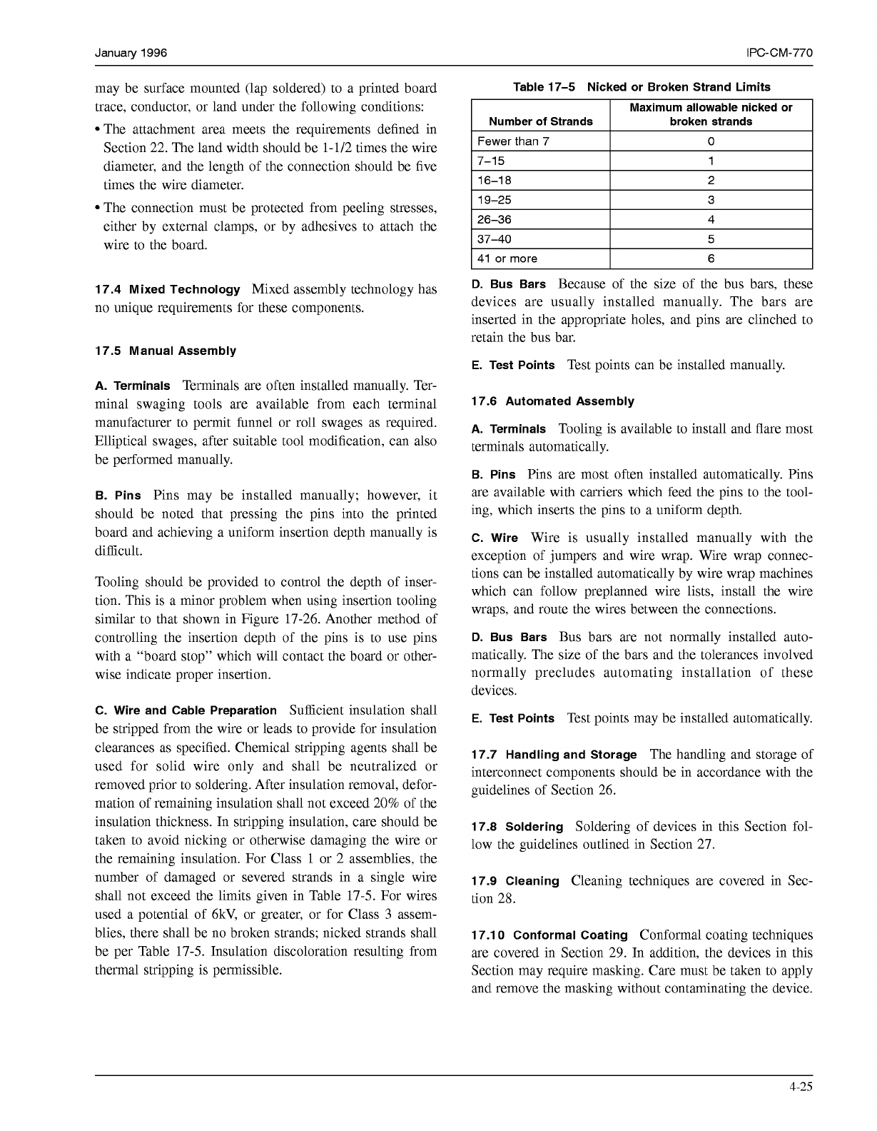
contain provisions which permit the heat sink and compo-
This section provides information concerning Some of the nent leads to be soldered directly to the board. See Figure
many types of components that are used for the transfer-
18-2.
ence of heat, securing of parts to an assembly, maintaining
a prescribed space between part and surface, providing
electrical insulation between parts and guides used for
installing plug in assemblies. (Note: screws, rivets, wash-
ers, nuts, etc., are mentioned only in the application
required.)
18.1 Part Type Description
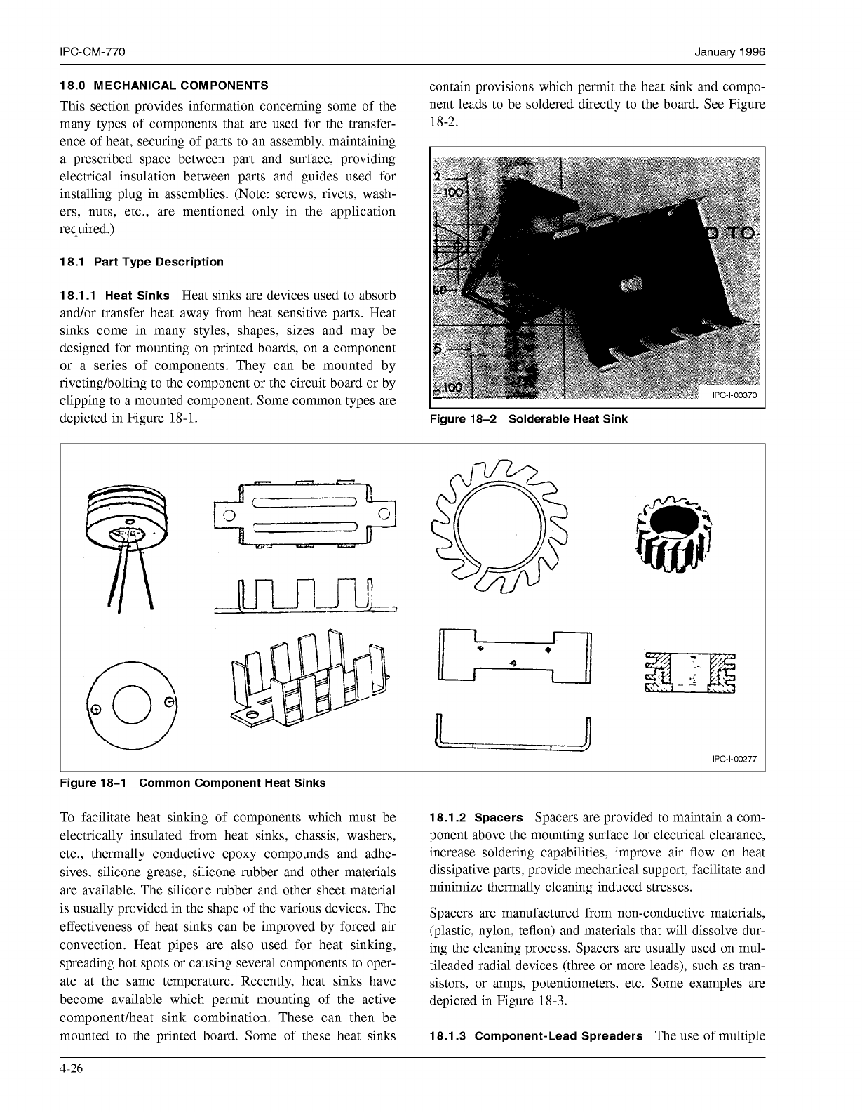
18.1.1 Heat Sinks
Heat sinks are devices used to absorb
and/or transfer heat away from heat sensitive parts. Heat
sinks come in many styles, shapes, sizes and may be
designed for mounting on printed boards, on a component
or a series of components. They can be mounted by
rivetingholting to the component or the circuit board or by
clipping to a mounted component. Some common types are
depicted in Figure
18-
1.
Figure 18-2 Solderable Heat Sink
I
1
n
o
*
n
U
I
I
U
9
IPC-1-00277
Figure 18-1 Common Component Heat Sinks
To facilitate heat sinking of components which must be
electrically insulated from heat sinks, chassis, washers,
etc., thermally conductive epoxy compounds and adhe-
sives, silicone grease, silicone rubber and other materials
are available. The silicone rubber and other sheet material
is usually provided in the shape of the various devices. The
effectiveness of heat sinks can be improved by forced air
convection. Heat pipes are also used for heat sinking,
spreading hot spots or causing several components to oper-
ate at the same temperature. Recently, heat sinks have
become available which permit mounting of the active
componentlheat sink combination. These can then be
mounted to the printed board. Some of these heat sinks
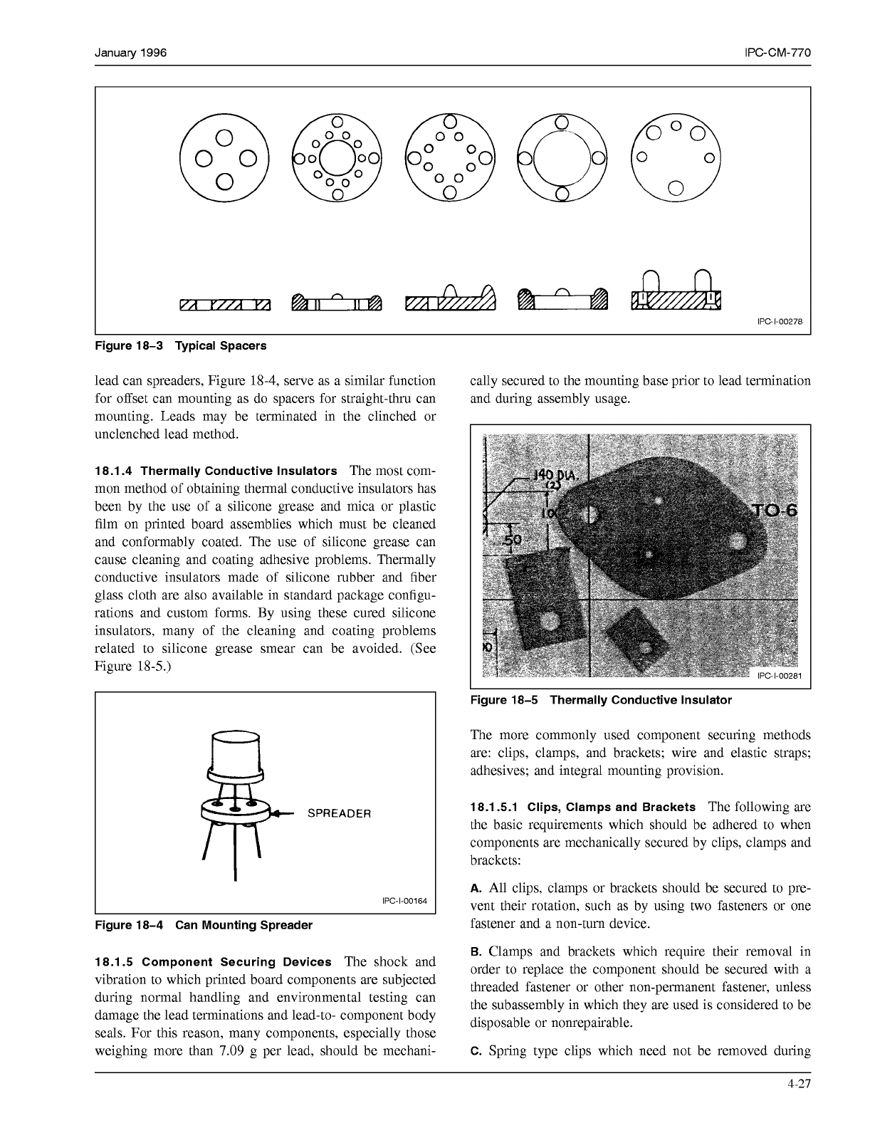
18.1.2 Spacers
Spacers are provided to maintain a com-
ponent above the mounting surface for electrical clearance,
increase soldering capabilities, improve air flow on heat
dissipative parts, provide mechanical support, facilitate and
minimize thermally cleaning induced stresses.
Spacers are manufactured from non-conductive materials,
(plastic, nylon, teflon) and materials that will dissolve dur-
ing the cleaning process. Spacers are usually used on mul-
tileaded radial devices (three or more leads), such as tran-
sistors, or amps, potentiometers, etc. Some examples are
depicted in Figure
18-3.
18.1.3 Component-Lead Spreaders
The use of multiple
4-26
COPYRIGHT Association Connecting Electronics Industries
Licensed by Information Handling Services
COPYRIGHT Association Connecting Electronics Industries
Licensed by Information Handling Services
January
1996
IPC-CM-770
@@O00
O
O0
o
O0
O
O
IPC-1-00278
Figure 18-3 Typical Spacers
lead can spreaders, Figure
18-4,
serve as a similar function
for offset can mounting as do spacers for straight-thru can
mounting. Leads may be terminated in the clinched or
unclenched lead method.
cally secured to the mounting base prior to lead termination
and during assembly usage.
I
18.1.4 Thermally Conductive Insulators
The most com-
mon method of obtaining thermal conductive insulators has
been by the use of a silicone grease and mica or plastic
film on printed board assemblies which must be cleaned
and conformably coated. The use of silicone grease can
cause cleaning and coating adhesive problems. Thermally
conductive insulators made of silicone rubber and fiber
glass cloth are also available in standard package configu-
rations and custom forms. By using these cured silicone
insulators, many of the cleaning and coating problems
related to silicone grease smear can be avoided. (See
Figure
18
-5
.)
Figure 18-5 Thermally Conductive Insulator
SPREADER
IPC-1-00164
I
L
Figure 18-4 Can Mounting Spreader
18.1.5 Component Securing Devices
The shock and
vibration to which printed board components are subjected
during normal handling and environmental testing can
damage the lead terminations and lead-to- component body
seals. For this reason, many components, especially those
weighing more than
7.09
g per lead, should be mechani-
The more commonly used component securing methods
are: clips, clamps, and brackets; wire and elastic straps;
adhesives; and integral mounting provision.
18.1 5.1 Clips, Clamps and Brackets
The following are
the basic requirements which should be adhered to when
components are mechanically secured by clips, clamps and
brackets:
A.
All clips, clamps or brackets should be secured to pre-
vent their rotation, such as by using two fasteners or one
fastener and a non-turn device.
B.
Clamps and brackets which require their removal in
order to replace the component should be secured with a
threaded fastener or other non-permanent fastener, unless
the subassembly in which they are used is considered to be
disposable or nonrepairable.
C.
Spring type clips which need not be removed during
4-21
COPYRIGHT Association Connecting Electronics Industries
Licensed by Information Handling Services
COPYRIGHT Association Connecting Electronics Industries
Licensed by Information Handling Services