IPC-CM-770D-1996.pdf - 第77页
Januaw 1996 IPC-CM-770 FlJNNEL FLAT HOLLED IPC-1-00243 Figure 16-6 Styles of Low-Profile Grip Devives provided for an extremely wide assortment of component types. The major use, however, is for semiconductor pack- age s…
IPC-CM-770
Januaty
1996
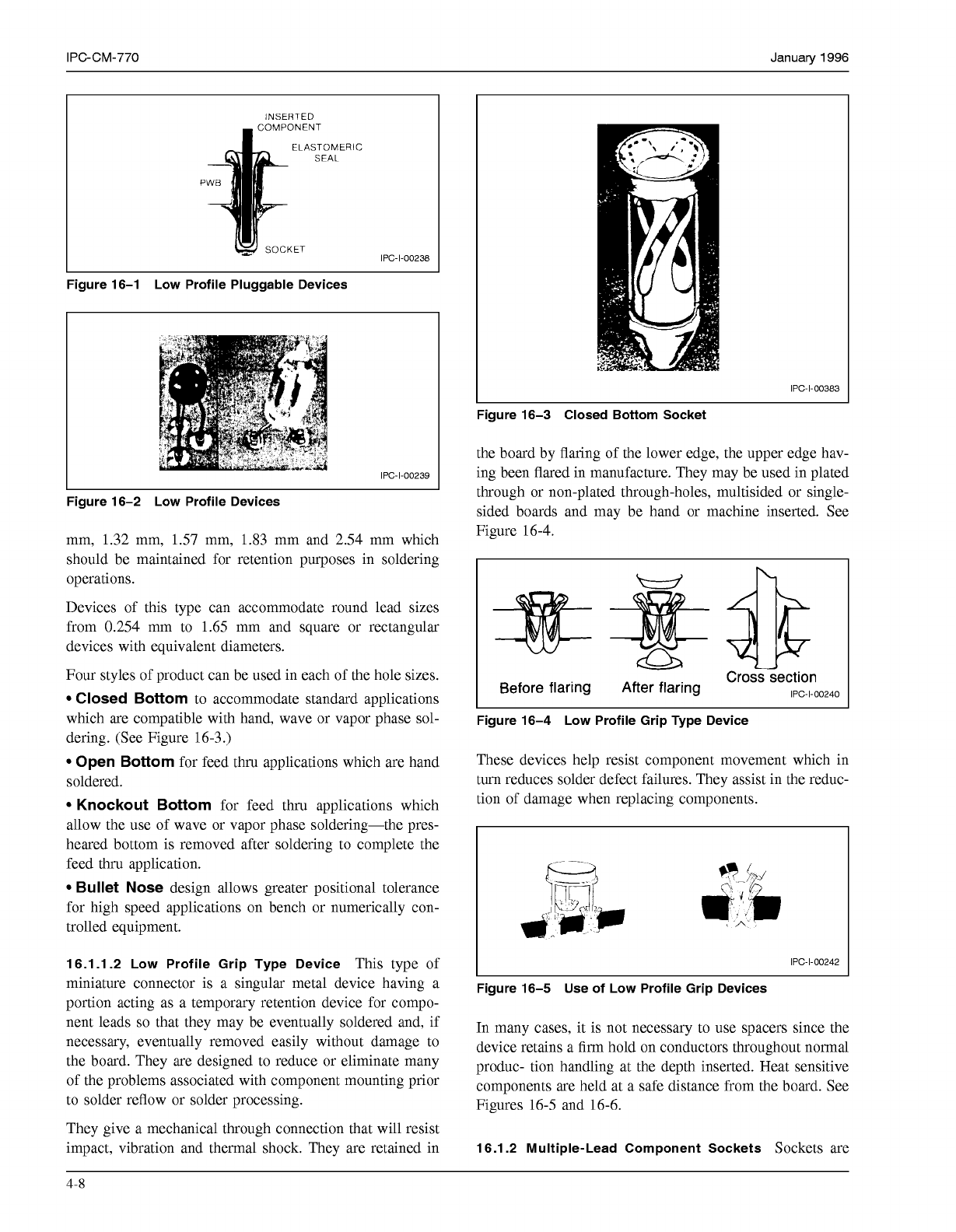
INSERTED
OMPONENT
ELASTOMERIC
SEAL
P
IPC-1-00238
Figure 16-1 Low Profile Pluggable Devices
Figure 16-2 Low Profile Devices
mm, 1.32 mm,
1.57
mm, 1.83 mm and 2.54 mm which
should be maintained for retention purposes in soldering
operations.
Devices of this type can accommodate round lead sizes
from 0.254 mm to 1.65 mm and square or rectangular
devices with equivalent diameters.
Four styles of product can be used in each of the hole sizes.
Closed Bottom
to accommodate standard applications
which are compatible with hand, wave or vapor phase sol-
dering. (See Figure 16-3.)
Open Bottom
for feed thru applications which are hand
soldered.
Knockout Bottom
for feed thru applications which
allow the use of wave or vapor phase soldering-the pres-
heared bottom is removed after soldering to complete the
feed thru application.
Bullet Nose
design allows greater positional tolerance
for high speed applications on bench or numerically con-
trolled equipment.
16.1.1.2 Low Profile Grip Type Device
This type of
miniature connector is a singular metal device having a
portion acting as a temporary retention device for compo-
nent leads
so
that they may be eventually soldered and, if
necessary, eventually removed easily without damage to
the board. They are designed to reduce or eliminate many
of the problems associated with component mounting prior
to solder reflow or solder processing.
They give a mechanical through connection that will resist
impact, vibration and thermal shock. They are retained in
I
IPC-1-00383
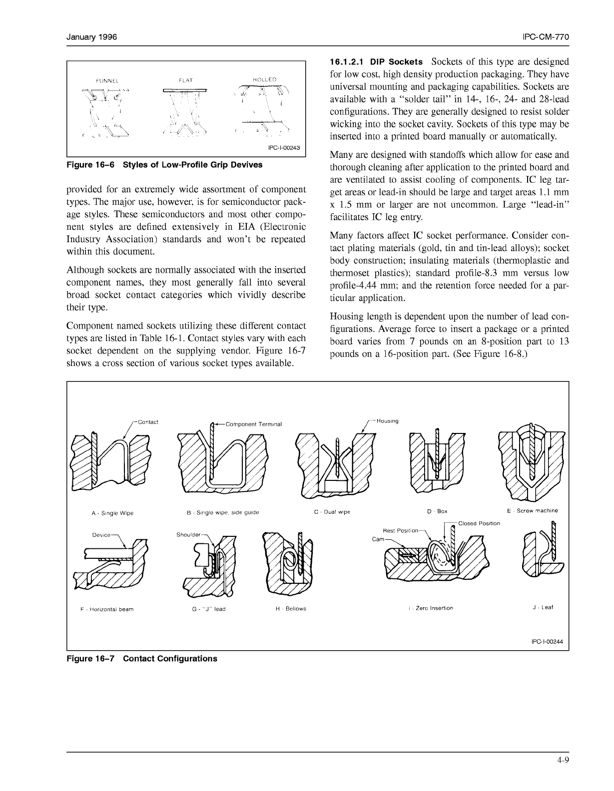
Figure 16-3 Closed Bottom Socket
the board by flaring of the lower edge, the upper edge hav-
ing been flared in manufacture. They may be used in plated
through or non-plated through-holes, multisided or single-
sided boards and may be hand or machine inserted. See
Figure 16-4.
I
Before flaring After flaring
Cross
section
IPC-I-O0240
Figure 16-4 Low Profile Grip Type Device
These devices help resist component movement which in
turn reduces solder defect failures. They assist in the reduc-
tion of damage when replacing components.
IPC-I-O0242
I
Figure 16-5 Use of Low Profile Grip Devices
In many cases, it is not necessary to use spacers since the
device retains a firm hold on conductors throughout normal
produc- tion handling at the depth inserted. Heat sensitive
components are held at a safe distance from the board. See
Figures 16-5 and 16-6.
16.1.2 Multiple-Lead Component Sockets
Sockets are
4-8
COPYRIGHT Association Connecting Electronics Industries
Licensed by Information Handling Services
COPYRIGHT Association Connecting Electronics Industries
Licensed by Information Handling Services
Januaw
1996
IPC-CM-770
FlJNNEL
FLAT
HOLLED
IPC-1-00243
Figure 16-6 Styles of Low-Profile Grip Devives
provided for an extremely wide assortment of component
types. The major use, however, is for semiconductor pack-
age styles. These semiconductors and most other compo-
nent styles are defined extensively in EIA (Electronic
Industry Association) standards and won't be repeated
within this document.
Although sockets are normally associated with the inserted
component names, they most generally fall into several
broad socket contact categories which vividly describe
their type.
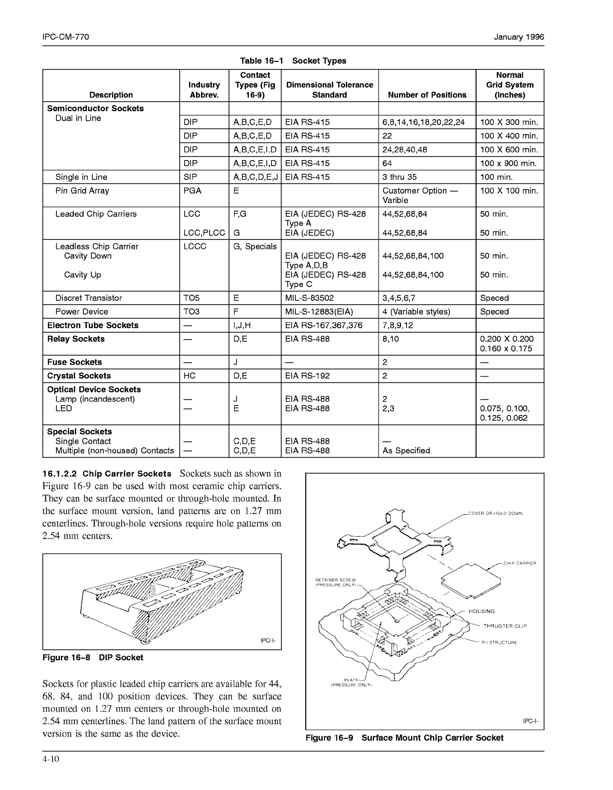
Component named sockets utilizing these different contact
types are listed in Table 16-1. Contact styles vary with each
socket dependent on the supplying vendor. Figure 16-7
shows a cross section of various socket types available.
16.1.2.1 DIP Sockets
Sockets of this type are designed
for low cost, high density production packaging. They have
universal mounting and packaging capabilities. Sockets are
available with a "solder tail" in 14-, 16-, 24- and 28-lead
configurations. They are generally designed to resist solder
wicking into the socket cavity. Sockets of this type may be
inserted into a printed board manually or automatically.
Many are designed with standoffs which allow for ease and
thorough cleaning after application to the printed board and
are ventilated to assist cooling of components. IC leg tar-
get areas or lead-in should be large and target areas
1.1
mm
x
1.5
mm or larger are not uncommon. Large "lead-in"
facilitates IC leg entry.
Many factors affect IC socket performance. Consider con-
tact plating materials (gold, tin and tin-lead alloys); socket
body construction; insulating materials (thermoplastic and
thermoset plastics); standard profile-8.3 mm versus low
profile-4.44 mm; and the retention force needed for a par-
ticular application.
Housing length is dependent upon the number of lead con-
figurations. Average force to insert a package or a printed
board varies from 7 pounds on an 8-position part to 13
pounds on a 16-position part. (See Figure 16-8.)
TContact
Houslng
A
-
Slngle Wlpe
Devlce-
B
~ Single wipe. slde gulde
C
~ Dual wlpe D ~
Box
E
~ Screw machlne
losed Posltlon
Rest
Posltlon
Cam
F
-
Horlzontal beam
G
-
"J"
lead
H
~ Bellows
1
~ Zero Insertion J ~ Leaf
IPC-1-00244
Figure 16-7 Contact Configurations
4-9
COPYRIGHT Association Connecting Electronics Industries
Licensed by Information Handling Services
COPYRIGHT Association Connecting Electronics Industries
Licensed by Information Handling Services
IPC-CM-770
Table 16-1 Socket Types
16.1.2.2 Chip Carrier Sockets
Sockets such as shown in
Figure 16-9 can be used with most ceramic chip carriers.
They can be surface mounted or through-hole mounted. In
the surface mount version, land patterns are on 1.27 mm
centerlines. Through-hole versions require hole patterns on
2.54 mm centers.
IPC-I-
I I
Figure 16-8
DIP
Socket
Sockets for plastic leaded chip carriers are available for 44,
68, 84, and
100
position devices. They can be surface
mounted on 1.27 mm centers or through-hole mounted on
2.54 mm centerlines. The land pattern of the surface mount
Januaty 1996
Normal
Grid System
(Inches)
100
X
300
min.
100
X
400
min.
100
X
600 min.
100
x
900 min.
100 min.
100
X
100 min.
50 min.
50 min.
50 min.
50 min.
Speced
Speced
7
0.200
x
0.200
0.160
x
0.175
-
0.075, 0.100,
0.125, 0.062
CHIP
CARPIER
(PRESSURE
ONLY
RETAINER SCREW
THRUSTER
CLIP
P
I
STRUCTURE
(PRESSURF
ONLY
IPC-I-
4-10
COPYRIGHT Association Connecting Electronics Industries
Licensed by Information Handling Services
COPYRIGHT Association Connecting Electronics Industries
Licensed by Information Handling Services