IPC-CM-770D-1996.pdf - 第165页
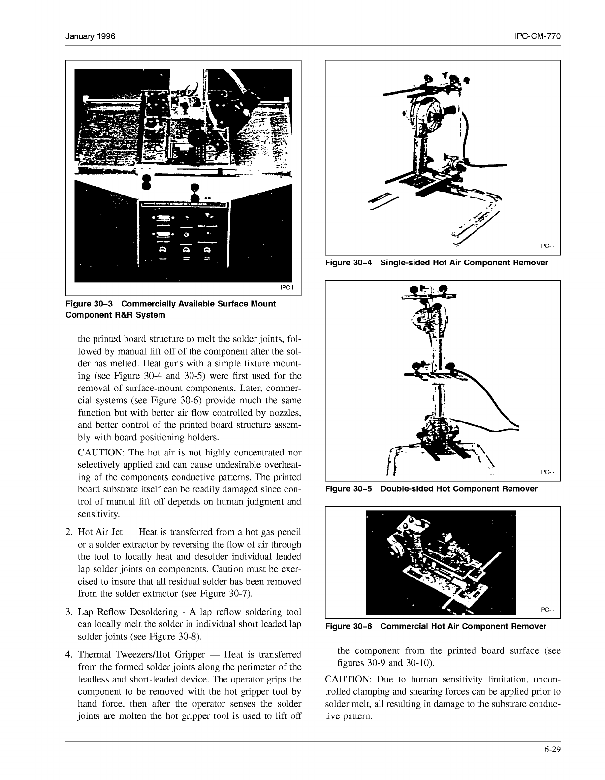
January 1996 IPC-CM-770 'igure 30-3 Commercially Available Surface Mount Component R&R System the printed board structure to melt the solder joints, fol- lowed by manual lift off of the component after the sol- …
IPC-CM-770
Januaty
1996
molten and if the component can be removed without
damage to the component, lands, conductor patterns or
plated-through holes.
Adhesive bonding of the component to the printed board
structure’s surface, can significantly increase the risk of
damaging the printed board structure using component
removal methods.
After the component has been removed the replacement
component can be inserted while the solder joints are still
molten, or the remaining solder must be removed from
the component mounting holes by a second operation.
With some equipment, the printed board structure is
maintained at soldering temperature for a longer period of
time in order to remove the solder from the holes using
an auxiliary part of the component removal equipment.
With other equipment, the printed board structure is
allowed to cool and the solder is removed using a sepa-
rate process.
The replacement component is then placed in position
and soldered in place.
Pin grid array component removal presents serious prob-
lems. This is due to the cooling sink action of the compo-
nent itself, the number of component leads, and the possi-
bility of blind hole solder joints. Pin grid arrays can be
removed, with various degrees of success, from printed
board assemblies using solder extraction with vacuum fol-
lowed by pressure component removal methods.
30.6.4 Surface Mounted Devices
A controlled process
for the Removal and Replacement (R&R) of surface
mounted devices (i.e., leadless, short leaded and long
leaded) is essential in repairing modern day electronic
assemblies. The process should allow for the R&R of an
individual component within the defined thermal, mechani-
cal and electrical requirements to assure sustaining the
quality of the original assembly.
A controlled surface mount removal and replacement pro-
cess requirements include:
Controlled application of heat to melt solder joints of the
SMD in question without causing the overheat of the base
material, or of any component, or the remelt of any adja-
cent solder joints.
Controlled lift
off
of the component after sensing solder
melt and to prevent delamination of the lands from the
printed board structure.
Preparation of the printed board lands and pre-tinning of
the SMD prior to replacement soldering.
Controlled positioning of the component on the P&I
structure land pattern.
Reflow soldering of the SMD solder joints with the con-
trolled heating.
30.6.4.1 Heating Methods
There are various methods
and devices available for removing and/or replacing
surface-mounted components. However, many of them
have specific limitations and must be used with appropriate
caution. Some of the heating methods that have been uti-
lized, attempted or proposed include Hot Air (or gas),
Vapor Phase, Infra-Red (IR), Hot Gripper, Hot Plate, Ther-
mal Tweezers, and a few other heat transfer methods.
While each of these methods can be made to work under
certain conditions, other equipment or methods may be
more suitable for the R&R task at hand. The following is a
description of some of the component removal and/or
replace methods and some of the cautions or other consid-
erations for each of the selected methods:
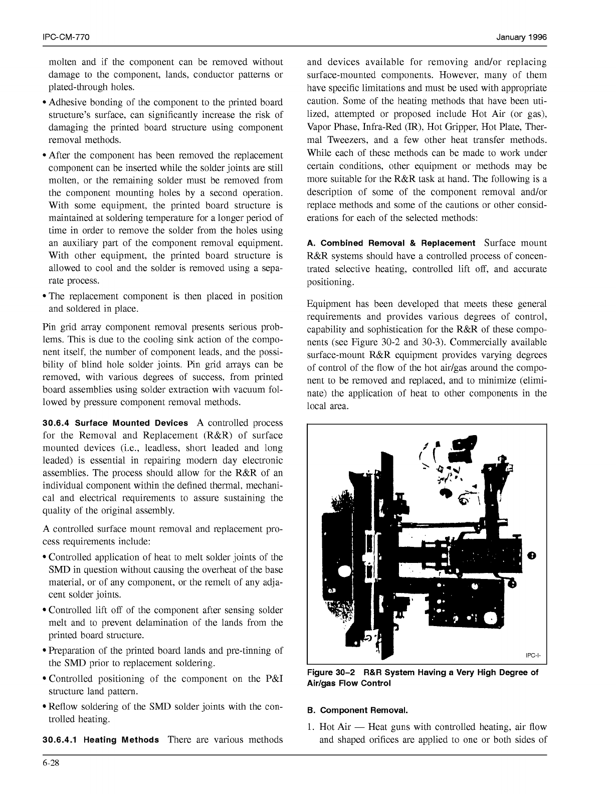
A. Combined Removal
&
Replacement
Surface mount
R&R systems should have a controlled process of concen-
trated selective heating, controlled lift
off,
and accurate
positioning.
Equipment has been developed that meets these general
requirements and provides various degrees of control,
capability and sophistication for the R&R of these compo-
nents (see Figure
30-2
and
30-3).
Commercially available
surface-mount R&R equipment provides varying degrees
of control of the flow of the hot aidgas around the compo-
nent to be removed and replaced, and to minimize (elimi-
nate) the application of heat to other components in the
local area.
Figure 30-2
R&R
System Having a Very High Degree of
Airlgas Flow Control
B.
Component Removal.
1.
Hot Air
-
Heat guns with controlled heating, air flow
and shaped orifices are applied to one or both sides of
6-28
COPYRIGHT Association Connecting Electronics Industries
Licensed by Information Handling Services
COPYRIGHT Association Connecting Electronics Industries
Licensed by Information Handling Services
January
1996
IPC-CM-770
'igure
30-3
Commercially Available Surface Mount
Component
R&R
System
the printed board structure to melt the solder joints, fol-
lowed by manual lift
off
of the component after the sol-
der has melted. Heat guns with a simple fixture mount-
ing (see Figure 30-4 and 30-5) were first used for the
removal of surface-mount components. Later, commer-
cial systems (see Figure 30-6) provide much the same
function but with better air flow controlled by nozzles,
and better control of the printed board structure assem-
bly with board positioning holders.
CAUTION: The hot air is not highly concentrated nor
selectively applied and can cause undesirable overheat-
ing of the components conductive patterns. The printed
board substrate itself can be readily damaged since con-
trol of manual lift
off
depends on human judgment and
sensitivity.
2.
Hot Air Jet
-
Heat is transferred from a hot gas pencil
or a solder extractor by reversing the flow of air through
the tool to locally heat and desolder individual leaded
lap solder joints on components. Caution must be exer-
cised to insure that all residual solder has been removed
from the solder extractor (see Figure 30-7).
3. Lap Reflow Desoldering
-
A lap reflow soldering tool
can locally melt the solder in individual short leaded lap
solder joints (see Figure 30-8).
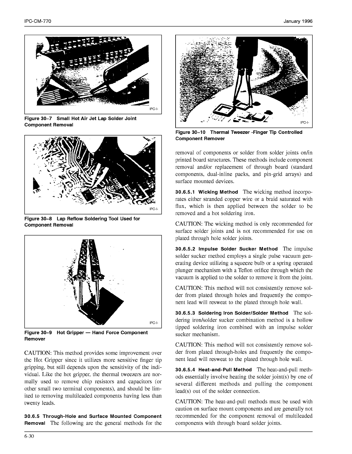
4. Thermal TweezerdHot Gripper
-
Heat is transferred
from the formed solder joints along the perimeter of the
leadless and short-leaded device. The operator grips the
component to be removed with the hot gripper tool by
hand force, then after the operator senses the solder
joints are molten the hot gripper tool is used to lift
off
Figure
30-4
Single-sided Hot Air Component Remover
IPC-I-
Figure
30-5
Double-sided Hot Component Remover
IPC-I-
Figure
30-6
Commercial Hot Air Component Remover
the component from the printed board surface (see
figures 30-9 and 30-10).
CAUTION: Due to human sensitivity limitation, uncon-
trolled clamping and shearing forces can be applied prior to
solder melt, all resulting in damage to the substrate conduc-
tive pattern.
6-29
COPYRIGHT Association Connecting Electronics Industries
Licensed by Information Handling Services
COPYRIGHT Association Connecting Electronics Industries
Licensed by Information Handling Services
IPC-CM-770
Januaty
1996
IPC-I-
Figure 30-7 Small Hot Air Jet Lap Solder Joint
Component Removal
IPC-I-
Figure 30-8 Lap Reflow Soldering Tool Used for
Component Removal
IPC-I-
Figure 30-9 Hot Gripper
-
Hand Force Component
Remover
CAUTION: This method provides some improvement over
the Hot Gripper since it utilizes more sensitive finger tip
gripping, but still depends upon the sensitivity of the indi-
vidual. Like the hot gripper, the thermal tweezers are nor-
mally used to remove chip resistors and capacitors (or
other small two terminal components), and should be lim-
ited to removing multileaded components having less than
twenty leads.
30.6.5 Through-Hole and Surface Mounted Component
Removal
The following are the general methods for the
I
Figure 30-10 Thermal Tweezer -Finger Tip Controlled
Component Remover
removal of components or solder from solder joints on/in
printed board structures. These methods include component
removal and/or replacement of through board (standard
components, dual-inline packs, and pin-grid arrays) and
surface mounted devices.
30.6.5.1 Wicking Method
The wicking method incorpo-
rates either stranded copper wire or a braid saturated with
flux, which is then applied between the solder to be
removed and a hot soldering iron.
CAUTION: The wicking method is only recommended for
surface solder joints and is not recommended for use on
plated through hole solder joints.
30.6.5.2 Impulse Solder Sucker Method
The impulse
solder sucker method employs a single pulse vacuum gen-
erating device utilizing a squeeze bulb or a spring operated
plunger mechanism with a Teflon orifice through which the
vacuum is applied to the solder to remove it from the joint.
CAUTION: This method will not consistently remove sol-
der from plated through holes and frequently the compo-
nent lead will resweat to the plated through hole wall.
30.6.5.3 Soldering Iron SolderlSolder Method
The sol-
dering irodsolder sucker combination method is a hollow
tipped soldering iron combined with an impulse solder
sucker mechanism.
CAUTION: This method will not consistently remove sol-
der from plated through-holes and frequently the compo-
nent lead will resweat to the plated through hole wall.
30.6.5.4 Heat-and-Pull Method
The heat-and-pull meth-
ods essentially involve heating the solder joint(s) by one of
several different methods and pulling the component
lead(s) out of the solder connection.
CAUTION: The heat-and-pull methods must be used with
caution on surface mount components and are generally not
recommended for the component removal of multileaded
components with through board solder joints.
6-30
COPYRIGHT Association Connecting Electronics Industries
Licensed by Information Handling Services
COPYRIGHT Association Connecting Electronics Industries
Licensed by Information Handling Services