00195760-0102_UM_D3_SR605_EN.pdf - 第111页
User Manual SIPLACE D3 3 Technical data for the machine From software version SR.605.xx 07/2008 EN Edition 3.5 Placement head 111 3.5.2 6-segment Collect&Place h ead for high-speed IC placement 3 Fig. 3.5 - 3 6-segme…

3 Technical data for the machine User Manual SIPLACE D3
3.5 Placement head From software version SR.605.xx 07/2008 EN Edition
110
Programmed power stage
1
2
3
4
5
Programmed set-down force [N]
2.4 ± 0.5
2.4 ± 0.5
3 + 1
4 + 1
5 + 1
Nozzle types 9xx 9xx
X/Y accuracy
c
± 45 μm/3σ, ± 60 μm/4σ ± 41 μm/3σ, ± 55 μm/4σ
Angular accuracy ± 0.5°/3 σ, ± 0.7°/4 σ ± 0.5°/3 σ, ± 0.7°/4 σ
Component range 98% 98.5%
CO camera type 28 29
Illumination level 5 5
Possible illumination level
settings
256
5
256
5
a) Please note that the component range that can be placed is also affected by the pad geometry, the cus-
tomer-specific standards and the packaging tolerances.
b) With 0201 package
c) The accuracy value was measured using the vendor-neutral IPC standard.
User Manual SIPLACE D3 3 Technical data for the machine
From software version SR.605.xx 07/2008 EN Edition 3.5 Placement head
111
3.5.2 6-segment Collect&Place head for high-speed IC placement
3
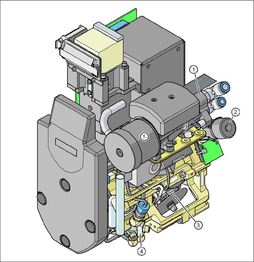
Fig. 3.5 - 3 6-segment Collect&Place head - Function groups, part 1
3
(1) Vacuum generator
(2) Turning station, DP axis
(3) Star with 6 sleeves - star axis
(4) Forced air valve
(5) Silencer
3 Technical data for the machine User Manual SIPLACE D3
3.5 Placement head From software version SR.605.xx 07/2008 EN Edition
112
3
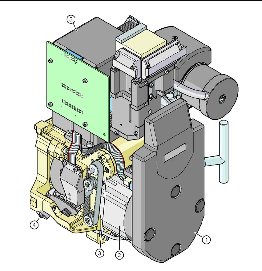
Fig. 3.5 - 4 6-segment Collect&Place head - Function groups, part 2
3
(1) Intermediate distributor board, beneath the cover
(2) Star drive - DR motor
(3) Z axis motor
(4) Valve adjustment drive
(5) C&P CO camera