00195760-0102_UM_D3_SR605_EN.pdf - 第249页
User Manual SIPLACE D3 4 Setting up and commissioning From software version SR.605.xx 07/2008 EN Edition 4.5 Adapting the used tape channel 249 4.5 Adapting the used t ape channel If feeder m odules that process co mpone…
4 Setting up and commissioning User Manual SIPLACE D3
4.4 Adapting the component trolley to the PCB conveyor height From software version SR.605.xx 07/2008 EN Edition
248
→ Raise the component trolley bed slightly to expose the split pins (item 3 in Fig. 4.4 - 2).
→ Use the punch to carefully tap out the split pins on both sides.
→ Insert the spiral clamping pins into the holes for the required PCB conveyor height (see Fig.
4.4 - 1
).
→ Lower the component trolley bed slowly until the split pins lie on the supporting blocks (item
4 in Fig. 4.4 - 2
).
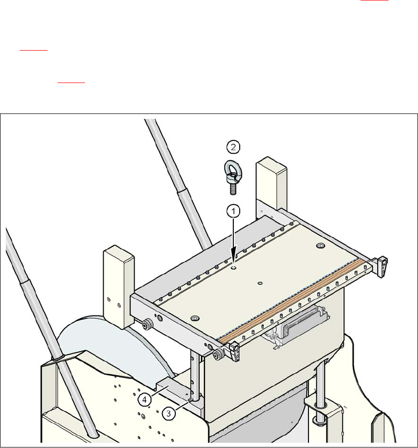
→ Unscrew the eye-bolt from the component trolley table.
4
Fig. 4.4 - 2 Position of the eye-bolt on the component trolley
(1) M12 hole for eye-bolt
(2) Eye-bolt, DIN 580 M12-St
(3) Spiral clamping pin, DIN 7343, 8x40 - St, 2x
(4) Supporting block, 2x
User Manual SIPLACE D3 4 Setting up and commissioning
From software version SR.605.xx 07/2008 EN Edition 4.5 Adapting the used tape channel
249
4.5 Adapting the used tape channel
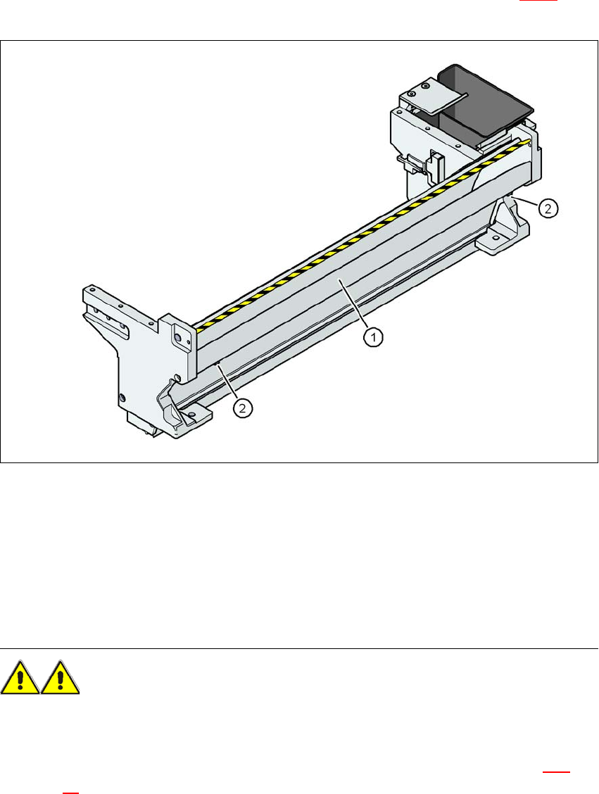
If feeder modules that process component tapes with a pocket height > 17 mm are used, such as,
for example, the 44 mm S DP feeder module, then the separating plate (item 3 in Fig. 4.5 - 1
) must
be removed.
4
Fig. 4.5 - 1 Used tape channel with component reject bin
(1) separating plate for tapes > 17 mm, removable
(2) DIN 84 - M3x6 screw, 2x
4
4
4.5.1 Safety instructions
WARNING 4
→ Switch the machine off at the main switch to remove the dividing plate.
→ Disconnect the machine from the power and compressed air supply.
→ Secure the machine to prevent it being switched on again, as described in Section 2.10
,
page 90
.

4 Setting up and commissioning User Manual SIPLACE D3
4.6 Commissioning the machine From software version SR.605.xx 07/2008 EN Edition
250
→ Wait until the operating pressure for the tape cutter has dropped to 0 MPa.
→ Wear robust protective gloves.
→ Do not reach inside the used tape channel.
4.5.2 Removing the separating plate
→ Loosen the two slotted screws (item 4 in Fig. 4.5 - 1, page 249)
→ Pull out the dividing plate.
4.6 Commissioning the machine
4.6.1 Commissioning the machine at the customer's premises
→ Check all modules for correct seating.
→ Wipe off the linear guide rails with a lint-free cloth before removing the shipping braces for the
X/Y axis. Do not use any solvent to do this (see Section 4.3.20
, page 245.
→ Switch on the machine and perform a reference run.
→ Copy the placement program onto the computer and test it.
→ Check the machine zero point after a period of warming up of 3 - 4 h.
→ Get the customer's operating personnel to equip the feeder modules according to the cus-
tomer's placement program.
→ Instruct them in handling the feeder modules using the JobGuide.
→ Check all customer-specific installed options (in particular software) for good functioning and
order any necessary spare parts using the order form or by fax.
4.6.2 Instructing the customer's personnel
→ Explain all customer-specific installed options, in particular software / software compatibility.
→ Explain programming of the program editors on the line computer / SIPLACE Pro.
→ Instruct the operators and line engineers in using the station software.
→ Explain about password protection.
→ Instruct the customer's personnel according to the user manual and preventive maintenance
manual.