00195760-0102_UM_D3_SR605_EN.pdf - 第15页
User Manual SIPLACE D3 1 Introduction From software version SR.605.xx 07/2008 EN Edition 15 1 Introduction These operating instructions pro vide a manual or refere nce work for oper ating and settin g up the SIPLACE ® D3…
Content User Manual SIPLACE D3
07/2008 EN Edition
14
6.9 Siemens interface . . . . . . . . . . . . . . . . . . . . . . . . . . . . . . . . . . . . . . . . . . . . . . . . . . . . . . . . . . . . . 326
6.10 Package for splice detection . . . . . . . . . . . . . . . . . . . . . . . . . . . . . . . . . . . . . . . . . . . . . . . . . . . . 326
6.11 Long board. . . . . . . . . . . . . . . . . . . . . . . . . . . . . . . . . . . . . . . . . . . . . . . . . . . . . . . . . . . . . . . . . . . 327
6.12 Magnetic pin support. . . . . . . . . . . . . . . . . . . . . . . . . . . . . . . . . . . . . . . . . . . . . . . . . . . . . . . . . . . 328
6.13 Feeder module cover flap . . . . . . . . . . . . . . . . . . . . . . . . . . . . . . . . . . . . . . . . . . . . . . . . . . . . . . . 329
6.14 Component sensor for the C&P12 head . . . . . . . . . . . . . . . . . . . . . . . . . . . . . . . . . . . . . . . . . . . 330
6.14.1 Description of the component sensor . . . . . . . . . . . . . . . . . . . . . . . . . . . . . . . . . . . 331
6.14.2 Working principle . . . . . . . . . . . . . . . . . . . . . . . . . . . . . . . . . . . . . . . . . . . . . . . . . . 331
6.14.3 Using the component sensor . . . . . . . . . . . . . . . . . . . . . . . . . . . . . . . . . . . . . . . . . 332
6.15 High-resolution CO camera for the 12-segment C&P head,
type 29. . . . . . . . . . . . . . . . . . . . . . . . . . . . . . . . . . . . . . . . . . . . . . . . . . . . . . . . . . . . . . . . . . . . . . . 333
6.15.1 Structure . . . . . . . . . . . . . . . . . . . . . . . . . . . . . . . . . . . . . . . . . . . . . . . . . . . . . . . . . 333
6.15.2 Technical data . . . . . . . . . . . . . . . . . . . . . . . . . . . . . . . . . . . . . . . . . . . . . . . . . . . . 333
6.16 0201 package . . . . . . . . . . . . . . . . . . . . . . . . . . . . . . . . . . . . . . . . . . . . . . . . . . . . . . . . . . . . . . . . . 334
6.17 Coplanarity laser module . . . . . . . . . . . . . . . . . . . . . . . . . . . . . . . . . . . . . . . . . . . . . . . . . . . . . . . 334
6.17.1 Safety instructions for the sensor of the coplanarity module . . . . . . . . . . . . . . . . . 334
6.17.2 Description . . . . . . . . . . . . . . . . . . . . . . . . . . . . . . . . . . . . . . . . . . . . . . . . . . . . . . . 335
6.17.3 Technical data . . . . . . . . . . . . . . . . . . . . . . . . . . . . . . . . . . . . . . . . . . . . . . . . . . . . 336
6.17.4 Restrictions. . . . . . . . . . . . . . . . . . . . . . . . . . . . . . . . . . . . . . . . . . . . . . . . . . . . . . . 336
6.17.5 Identify machine with warning label W216 . . . . . . . . . . . . . . . . . . . . . . . . . . . . . . . 337
6.17.6 LED displays on the controller . . . . . . . . . . . . . . . . . . . . . . . . . . . . . . . . . . . . . . . . 338
6.18 Vacuum pump . . . . . . . . . . . . . . . . . . . . . . . . . . . . . . . . . . . . . . . . . . . . . . . . . . . . . . . . . . . . . . . . 340
6.19 SIPLACE Productivity Lift. . . . . . . . . . . . . . . . . . . . . . . . . . . . . . . . . . . . . . . . . . . . . . . . . . . . . . . 341
6.19.1 Concept of parallel placement . . . . . . . . . . . . . . . . . . . . . . . . . . . . . . . . . . . . . . . . 341
6.19.2 Implementing parallel placement . . . . . . . . . . . . . . . . . . . . . . . . . . . . . . . . . . . . . . 342
6.19.3 Advantages of the productivity lift. . . . . . . . . . . . . . . . . . . . . . . . . . . . . . . . . . . . . . 343
6.20 Vision Teach Station . . . . . . . . . . . . . . . . . . . . . . . . . . . . . . . . . . . . . . . . . . . . . . . . . . . . . . . . . . . 344
6.20.1 Description . . . . . . . . . . . . . . . . . . . . . . . . . . . . . . . . . . . . . . . . . . . . . . . . . . . . . . . 345
6.20.2 Advantages . . . . . . . . . . . . . . . . . . . . . . . . . . . . . . . . . . . . . . . . . . . . . . . . . . . . . . 345
6.20.3 Which component cameras are supported?. . . . . . . . . . . . . . . . . . . . . . . . . . . . . . 346
User Manual SIPLACE D3 1 Introduction
From software version SR.605.xx 07/2008 EN Edition
15
1 Introduction
These operating instructions provide a manual or reference work for operating and setting up the
SIPLACE
®
D3 placement machine.
The header of each chapter contains the release and software version, to which this manual ap-
plies.
1
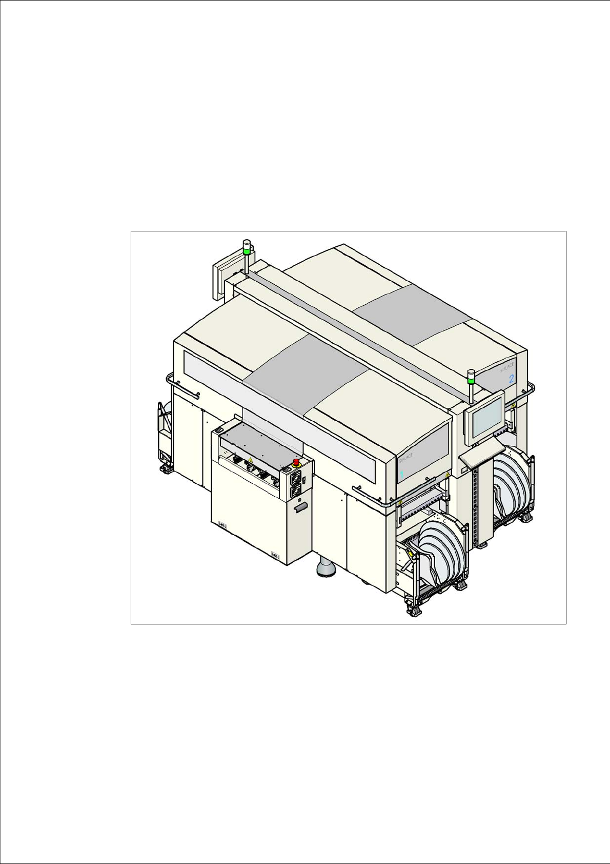
Fig. 1.0 - 1 SIPLACE D3 placement machine
1 Introduction User Manual SIPLACE D3
1.1 Description of the machine From software version SR.605.xx 07/2008 EN Edition
16
1.1 Description of the machine
1.1.1 SIPLACE D3 placement machine
The SIPLACE D3 placement machine is characterized by its high configuration flexibility, excellent
placement rate and maximum precision. The machine covers the SMD spectrum of components
from 0201 to 125 x 10 mm² with a high placement rate.
Two placement methods are used:
– the Collect&Place method with Collect&Place heads for components from size 0201 to fine-
pitch
– the Pick&Place method with the SIPLACE TwinHead for fine-pitch and OSC components
The placement machine is based on a torsionally-rigid and vibration-damped cast steel machine
frame. This guarantees an excellent production quality and less environmental pollution for em-
ployees since the noise of shaking and vibration are reduced to a minimum.
The placement machine has three gantries. There is a placement head on each gantry. These can
be quickly and accurately positioned, moving independently of one another in the X and Y direc-
tions.
Depending on the placement job, a 6-segment or a 12-segment Collect&Place head or a Twin-
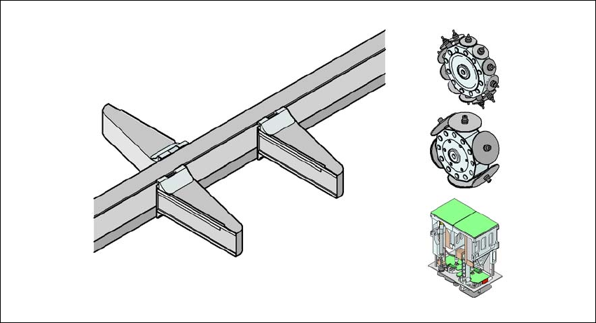
Head can be set up. This allows the following configurations:
1
1
Fig. 1.1 - 1 Head modularity - SIPLACE D3
Placement area 2
TH
C&P12
G1
G3
G4
C&P12/C&P6/TH
C&P12/C&P6/TH
C&P6
Placement area 1
C&P12/C&P6/TH