00195760-0102_UM_D3_SR605_EN.pdf - 第216页
4 Setting up and commissioning User Manual SIPLACE D3 4.3 Setting up the machine From software version SR.605.xx 07/2008 EN Edition 216 → Remove the ca ble covers (items 3 and 5 in Fig. 4.3 - 12 , pa ge 215 ) from the in…
User Manual SIPLACE D3 4 Setting up and commissioning
From software version SR.605.xx 07/2008 EN Edition 4.3 Setting up the machine
215
4.3.9 Fitting the input conveyor
4.3.9.1 Tools
– Allen keys, DIN 911, set
– Phillips screwdriver, size 1
4.3.9.2 Assembly
4
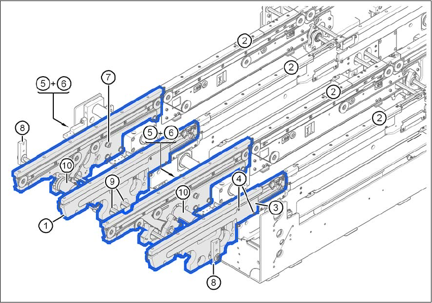
Fig. 4.3 - 12 Input conveyor - dual conveyor
(1) Rail, input conveyor
(2) Rail, processing conveyor 1
(3) Cable cover 20 x 200
(4) Countersunk screw, ISO 7046, M3x6, 2x per cable cover
(5) Cable cover 20 x 310
(6) Fillister head screw DIN 912, M3x5, 1x per cable cover
(7) Fillister head screw DIN 912, M6x16, and washer, 4x per rail
(8) Guide for hexagonal shaft
(9) Hexagonal shaft (single conveyor: one, dual conveyor: two)
(10) Drive unit

4 Setting up and commissioning User Manual SIPLACE D3
4.3 Setting up the machine From software version SR.605.xx 07/2008 EN Edition
216
→ Remove the cable covers (items 3 and 5 in Fig. 4.3 - 12, page 215) from the input conveyor
(item 1 in Fig. 4.3 - 12
, page 215).
→ Carefully place the rail (item 1 in Fig. 4.3 - 12
, page 215) against the rail on the processing
conveyor (item 2 in Fig. 4.3 - 12
, page 215).
CAUTION 4
Be careful not to cut through any of the light barrier or drive motor cables.
→ Fix each rail using 4 fillister head screws M6x16 and the associated washers (item 7 in Fig.
4.3 - 12
, page 215).
→ Connect the power cable to the light barriers and drive motors.
→ Fix the cable covers in place (item 3 and 5 in Fig. 4.3 - 12
, page 215).
→ Introduce the hexagonal shaft (item 9 in Fig. 4.3 - 12
, page 215) into the drive unit (item 10 in
Fig. 4.3 - 12
, page 215).
→ Make sure that the hexagonal shaft guide (item 8 in Fig. 4.3 - 12
, page 215) always points
towards the conveyor side wall to which the drive unit (item 10 in Fig. 4.3 - 12
, page 215) is
fixed.
User Manual SIPLACE D3 4 Setting up and commissioning
From software version SR.605.xx 07/2008 EN Edition 4.3 Setting up the machine
217
4.3.10 Fitting the extension kit on the PCB input side
4.3.10.1 Tools
– Allen keys, DIN 911, set
– Machine key
4.3.10.2 Assembly
4
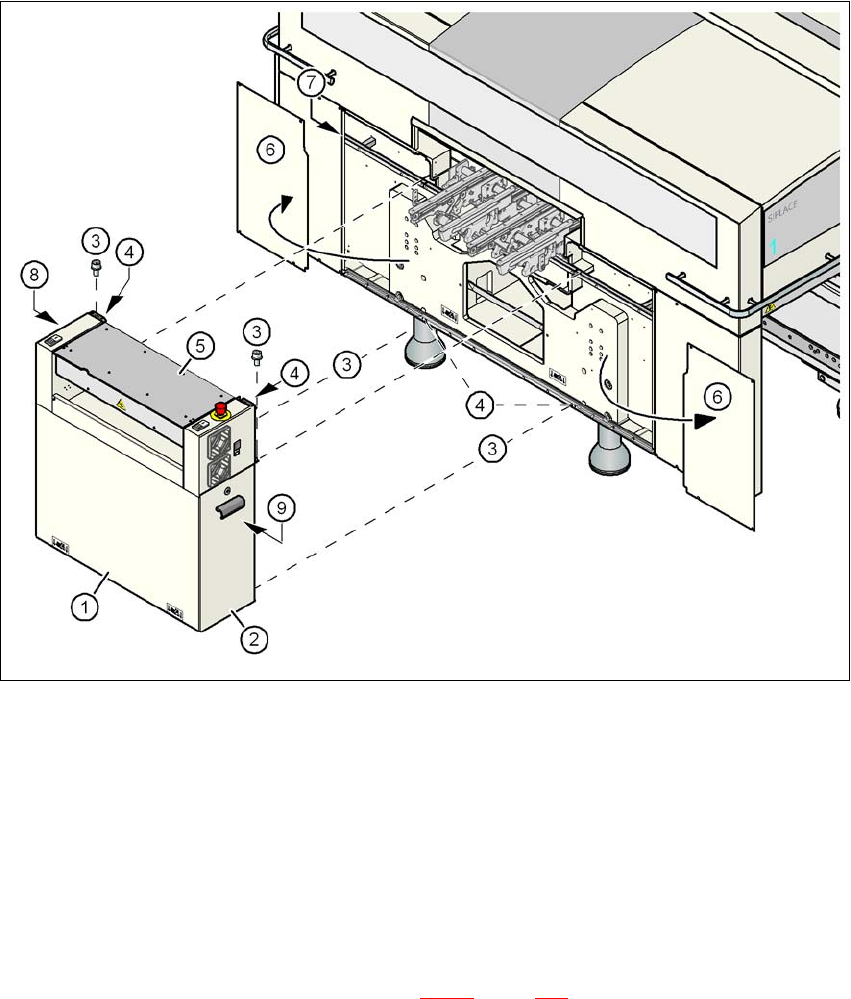
Fig. 4.3 - 13 Fitting the extension kit on the PCB input side
(1) Extension kit, dismantled
(2) Door
(3) Fillister head screw DIN 912, M6x16 and washer
(4) Ground connection point
(5) Conveyor cover
(6) Side panel, detached
(7) Drawer unit rail
(8) Computer unit or box PC unit (see Section 4.3.11
, page 221)
(9) Axis unit