00195760-0102_UM_D3_SR605_EN.pdf - 第233页
User Manual SIPLACE D3 4 Setting up and commissioning From software version SR.605.xx 07/2008 EN Edition 4.3 Setting up the machine 233 4 Fig. 4.3 - 21 Fitting the indicator lamp (1) Indicator lamp (2) Hole for the indic…

4 Setting up and commissioning User Manual SIPLACE D3
4.3 Setting up the machine From software version SR.605.xx 07/2008 EN Edition
232
4
→ Check the switch settings for S1
1: OFF
2: not used
4.3.13.3 Fitting the axis unit (gantry 1 and gantry 4)
→ Carefully lift the axis unit onto the rail in the extension kit.
→ Make sure that you do not squash any cables.
→ Push the axis unit into the extension kit as far as the stop.
→ Secure the axis unit with the fillister head screw.
→ Insert the cover.
→ Fix the grounding cable to the doors (item 2 in Fig. 4.3 - 13
, page 217),
as shown in Fig. 4.3 - 14
on page 220.
→ Lock the doors.
4.3.13.4 Fitting the side plates
→ Fix the grounding cable to each side plate (item 6 in Fig. 4.3 - 13, page 217), as shown in Fig.
4.3 - 14
page 220.
→ Fix the side plate to the machine frame with 6 fillister head screws.
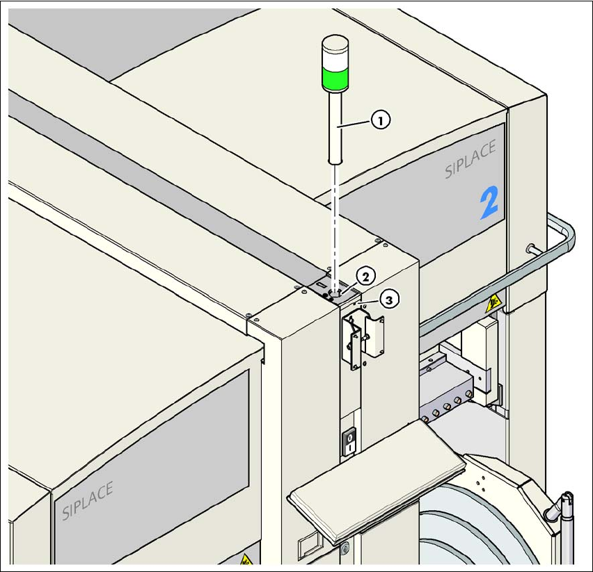
4.3.14 Fitting the indicator lamps
→ Connect the cables of the indicator lamps to the cables on the basic machine.
→ Insert the indicator lamp into the hole (item 2 in Fig. 4.3 - 21
, page 233) until the tube of the
indicator lamp projects sufficiently into the terminal beneath.
→ Tighten the hexagon socket head screw beneath the hole (item 3 in Fig. 4.3 - 21
, page 233).
X09_3tq X09_3tq 03050886 Snap connector into place
X10_3tq X10_3tq 03050885 Snap connector into place
X11_3tq X11_3tq 03050916 Snap connector into place
X12_3tq X12_3tq 03050915 Snap connector into place
X30_1tq
X30_2tq
X30_1tq
X30_2tq
03010051
03010051
Screw tightly
Axis unit, plugs Connecting cable PLEASE NOTE
Plug Cable
User Manual SIPLACE D3 4 Setting up and commissioning
From software version SR.605.xx 07/2008 EN Edition 4.3 Setting up the machine
233
4
Fig. 4.3 - 21 Fitting the indicator lamp
(1) Indicator lamp
(2) Hole for the indicator lamp
(3) Hole for the locking screw
4.3.15 Fixing the monitors
→ Fix the monitors and connect the cables.
→ Check the cable connections
4 Setting up and commissioning User Manual SIPLACE D3
4.3 Setting up the machine From software version SR.605.xx 07/2008 EN Edition
234
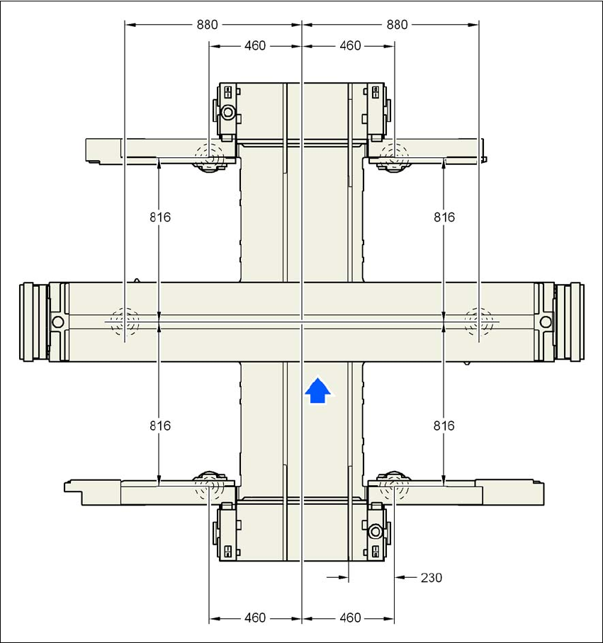
4.3.16 Machine foot clearances and the stationary PCB conveyor edges
4.3.16.1 Machine foot clearances and the stationary right conveyor edge for the
PCB single conveyor
4
Fig. 4.3 - 22 Machine foot clearances and the stationary right conveyor edge for the PCB single conveyorin millime-
ters