00195760-0102_UM_D3_SR605_EN.pdf - 第260页
5 Tasks for the operating personnel User Manual SIPLACE D3 5.2 Controls and displays From software version SR.605.xx 07/2008 EN Edition 260 5.2.3.1 Controls on the machine's operator p anels The two operator p anel …

User Manual SIPLACE D3 5 Tasks for the operating personnel
From software version SR.605.xx 07/2008 EN Edition 5.2 Controls and displays
259
Component barcode scanner 5
On each side of the middle console there is a bracket that holds the Datalogic DL 910 component
barcode scanner. The barcode scanner enables the components to be set up and topped up
quickly and reliably.
5.2.3 Ergonomic arrangement of the controls
Figure 5.2 - 1 on page 257 provides an overview of the position of the controls. They are subdi-
vided into the following groups:
Operator panel on the right-hand side (pneumatic unit) of the center console with 5
– LCD touchscreen
– Keyboard with trackball
– Start button, stop button
Operator panel on the left-hand side (power supply unit) of the center console with 5
– LCD touchscreen
– Keyboard with trackball
– Component counter
– Start button
– Stop button
– Main power switch
Input / output side of the PCB conveyor with 5
– EMERGENCY STOP button
– Start button, stop button
– Button for docking the component trolley in and out
5 Tasks for the operating personnel User Manual SIPLACE D3
5.2 Controls and displays From software version SR.605.xx 07/2008 EN Edition
260
5.2.3.1 Controls on the machine's operator panels
The two operator panel have identical control functions.
Monitor, keyboard, start and stop buttons 5
There is a monitor and a keyboard on both sides of the machine.
The start and stop buttons are located beneath the keyboard. The on-screen dialog will occasion-
ally prompt you to activate certain actions using buttons, and this arrangement will make it easier
for you both to activate and to interactively control these actions.
Main power switch 5
The main power switch is part of the power module. It is located on the left-hand operator panel
viewed in the direction of PCB transport. It is located here because it is only needed for servicing
and preventive maintenance work and is therefore not subject to frequent use.
5.2.3.2 Controls on the input and output sides of the machine
The controls on the input and output sides of the machine perform identical functions.
EMERGENCY STOP buttons, start and stop buttons 5
There is an EMERGENCY STOP button and start and stop buttons on both the input and output
sides of the PCB conveyor. This arrangement was adopted for the buttons because it enables
them to be reached quickly and easily from any position.
User Manual SIPLACE D3 5 Tasks for the operating personnel
From software version SR.605.xx 07/2008 EN Edition 5.3 Note operating status indicator lamp
261
5.3 Note operating status indicator lamp
The indicator lamp is used to signal operating statuses and malfunctions of the machine.
5.3.1 Description of the functions
5
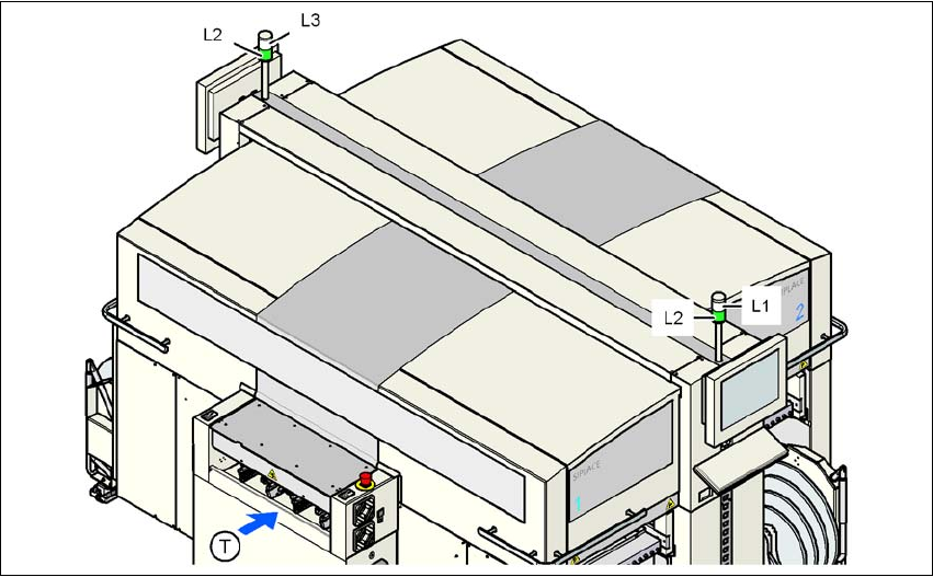
Fig. 5.3 - 1 Operating status indicator lamp
L1 Fault indicator lamp (white, right)
L2 Operating status indicator lamp (green, both lamps switched in parallel)
L3 Fault indicator lamp (white, left)
T Direction of PCB transport
5.3.2 General operating statuses
– Operating status indicator lamp L2 (green) on continuously
The machine is in service.
– Operating status indicator lamp L2 (green) flashes
The machine is waiting for a PCB on the input belt or the machine is waiting until the output
belt is free.
– Right fault indicator lamp L1 (white) flashes
One or more tracks are empty on the right-hand side of the machine. The machine continues
to place any remaining components.