00195760-0102_UM_D3_SR605_EN.pdf - 第298页
6 Station extensions User Manual SIPLACE D3 6.1 Nozzle changer From software version SR.605.xx 07/2008 EN Edition 298 6.1.3.3 Position of the nozzle changers for t he T winHead A nozzle change r may be installed for the …
User Manual SIPLACE D3 6 Station extensions
From software version SR.605.xx 07/2008 EN Edition 6.1 Nozzle changer
297
6.1.3 Nozzle changer for the SIPLACE TwinHead
Item no. 03005191-xx Magazine for 2 nozzles
Item no. 03001807-xx Magazine for 1 nozzle
6
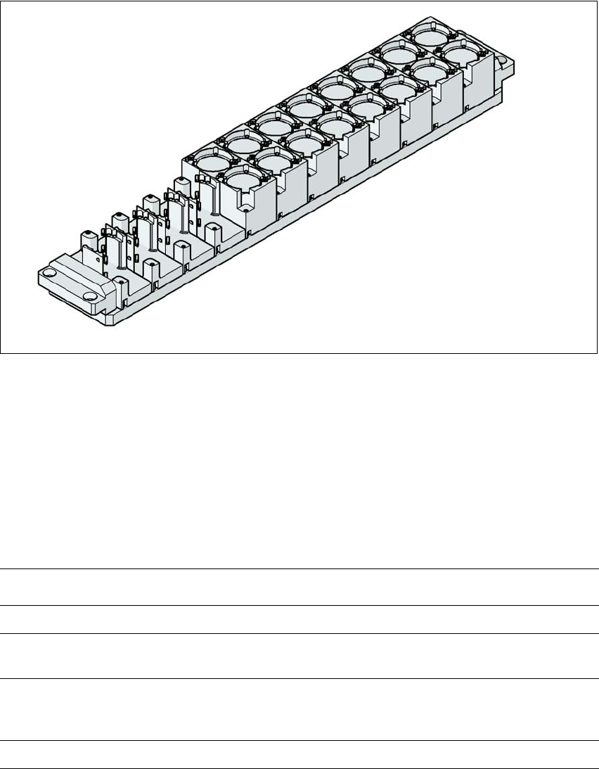
Fig. 6.1 - 13 Nozzle changers for the SIPLACE TwinHead
6.1.3.1 Description
This nozzle changer can hold up to 12 nozzle magazines. There are two types of magazine avail-
able: standard magazines and magazines for special nozzles or grippers. The magazines are
seated on a common support. They are centered with two parallel pins and fixed in place with two
countersunk screws.
6.1.3.2 Technical data
6
Nozzle changers for the SIPLACE TwinHead
Dimensions (length x width x height) 448 x 68 x 49 mm³
Number of nozzle holders 16 for standard nozzles
4 for special nozzles or grippers
Nozzle types 5xx, standard
4xx with adapter
9xx with adapter
Nozzle changeover time approx. 2s per nozzle
6 Station extensions User Manual SIPLACE D3
6.1 Nozzle changer From software version SR.605.xx 07/2008 EN Edition
298
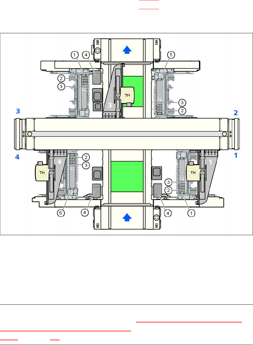
6.1.3.3 Position of the nozzle changers for the TwinHead
A nozzle changer may be installed for the TwinHead at locations 1 to 4.
Nozzle changer 1 at locations 1 and 3 (item 1 in Fig. 6.1 - 14
): 12 magazines each
Nozzle changer 2 at locations 2 and 4 (item 5 in Fig. 6.1 - 14
): 10 magazines
This gives a total capacity of 4 nozzle changers with 44 magazines and a total of 88 nozzle hold-
ers.
6
Fig. 6.1 - 14 Position of the nozzle changers for the TwinHead on the machine
(1) Nozzle changer 1
(2) Standard magazine
(3) Magazine for special nozzles or grippers
(4) Component reject bin
(5) Nozzle changer 2
PLEASE NOTE 6
If there is an MTC2 installed at location 4, then the "Nozzle changer for the TwinHead in the
placement area with 2 gantries and docked MTC2" option must be set up there (see Section
6.1.3.5, from page 300).
User Manual SIPLACE D3 6 Station extensions
From software version SR.605.xx 07/2008 EN Edition 6.1 Nozzle changer
299
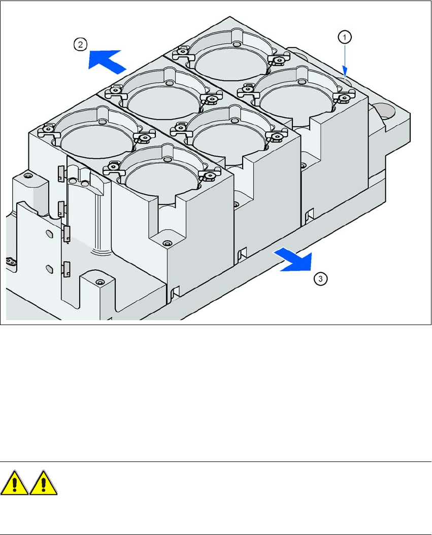
6.1.3.4 Assembly
The nozzle changer is fixed to the component trolley docking unit.
6
Fig. 6.1 - 15 Assembly position
(1) Marking hole
(2) Operator side
(3) Arrow pointing toward the PCB conveyor
6
→ Align the nozzle changer so that the marking hole (item 1) is on the left, as viewed by the op-
erator.
WARNING 6
Only install the associated nozzle changer for each placement head. There is a risk of head
crashes with mixed configurations.