00195760-0102_UM_D3_SR605_EN.pdf - 第176页
3 Technical data for the machine User Manual SIPLACE D3 3.10 Component trolley From software version SR.605.xx 07/2008 EN Edition 176 3.10.1 1 Used t ape channel In the standa rd version, the used t ape ch annel can guid…
User Manual SIPLACE D3 3 Technical data for the machine
From software version SR.605.xx 07/2008 EN Edition 3.10 Component trolley
175
3.10.10 Used tape chute
3
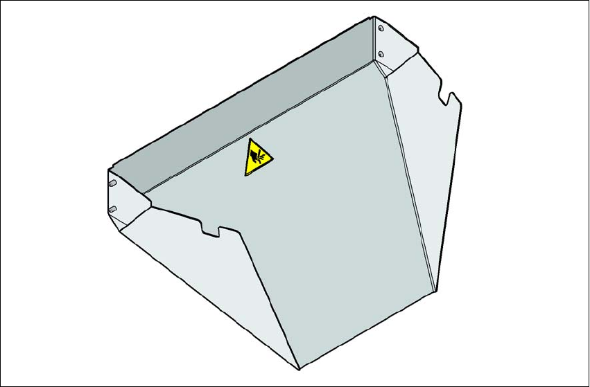
Fig. 3.10 - 9 Used tape chute
Attach the used tape chute to the component docking unit. The waste tape that is chopped up by
the tape cutter slides onto the used tape chute and into the waste container of the component trol-
ley.
3 Technical data for the machine User Manual SIPLACE D3
3.10 Component trolley From software version SR.605.xx 07/2008 EN Edition
176
3.10.11 Used tape channel
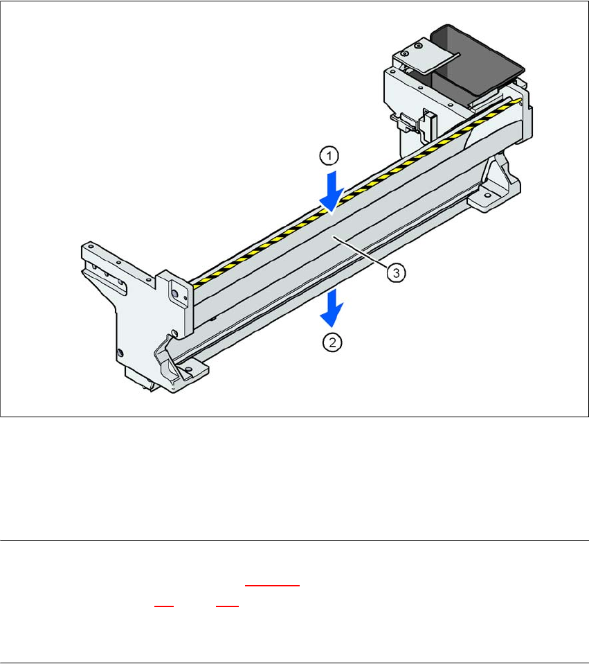
In the standard version, the used tape channel can guide component tapes with a maximum
pocket height of 17 mm to the pneumatic tape cutter.
3
Fig. 3.10 - 10 Used tape channel with component reject bin
(1) Inlet slot for the used tapes
(2) Outlet slot for the used tape above the pneumatic tape cutter
(3) Dividing plate for tapes < 17 mm (can be removed for tapes > 17 mm)
PLEASE NOTE
– The separating plate (item 3 in Fig. 3.10 - 10
) can be removed for tape pockets higher than
17 mm (see Section 4.5
, page 249).
→ Do not position feeder modules with shallow pockets immediately beside feeder modules with
deep pockets. The used tapes could overlap and build up.
User Manual SIPLACE D3 4 Setting up and commissioning
From software version SR.605.xx 07/2008 EN Edition 4.1 Transport and Delivery Configuration
177
4 Setting up and commissioning
4.1 Transport and Delivery Configuration
4.1.1 Shipping packaging
Within Europe, the machine and component trolleys will be shipped on two wooden pallets, pack-
aged in plastic film. Outside Europe, the machine and component trolleys are supplied in wooden
crates.
4.1.1.1 Dimensions of the shipping packaging
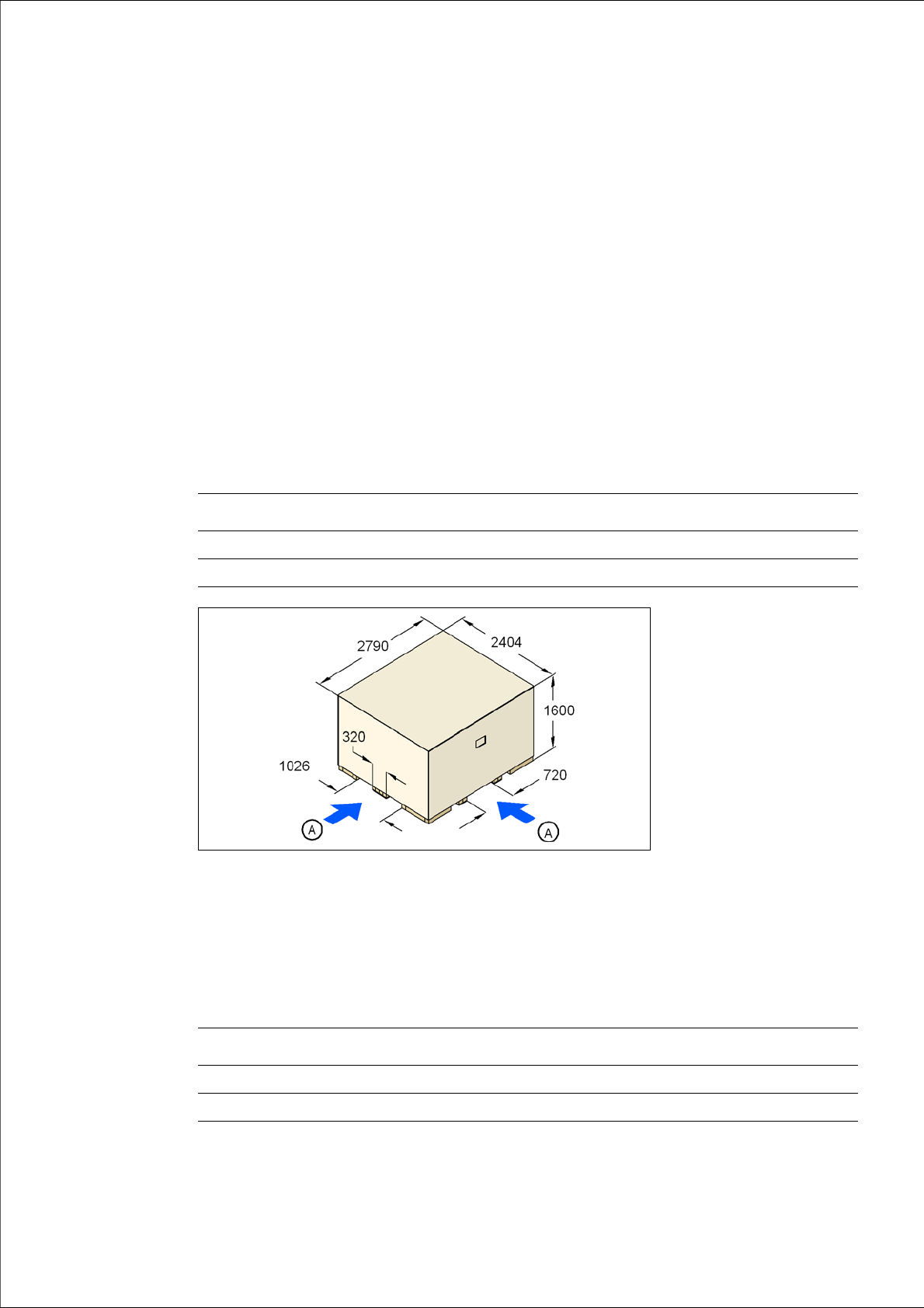
The dimensions of the pallets and wooden crates are listed in the following table:
4
Fig. 4.1 - 1 Transport crate - dimension in millimeters
(A) Fork-lift attachment points
4.1.1.2 Weight of the machine prepared for dispatch
The following table contains the weights of the machines prepared for dispatch, including packag-
ing.
Machine Component trolley
Pallet 2790 x 2404 mm² 2060 x 1350 mm²
Wooden crate 2790 x 2404 x 1600 mm³ 2060 x 1350 x 1300 mm³
Machine Dispatch within Europe Dispatch overseas
D3 3980 kg 4420 kg
Component trolley 470 kg 550 kg