00195760-0102_UM_D3_SR605_EN.pdf - 第337页
User Manual SIPLACE D3 6 Station extensions From software version SR.605.xx 07/2008 EN Edition 6.17 Coplanar ity laser module 337 6.17.5 Identify machine with warning label W216 6 W arning label W216 "Laser class 2 …

6 Station extensions User Manual SIPLACE D3
6.17 Coplanarity laser module From software version SR.605.xx 07/2008 EN Edition
336
The TwinHead picks up the component to be checked, centers it optically using the component
vision camera (see Section 6.6
, page 315) and moves all four sides one after another over the
fixed laser beam of the coplanarity laser module. In this way, every lead is scanned from below by
the laser beam. The laser light scattered by the underside of the lead is recorded by a sensor, and
is then used to calculate the exact position of the lead with respect to the PCB. The position values
thus calculated are compared against the limit value specified by the user. If they exceed this
value, the component is disposed of or returned.
The coplanarity laser module is used in combination with the optical component centering mode.
Components with bent or missing leads are detected and disposed of, if necessary.
6.17.3 Technical data
6
6
6
6.17.4 Restrictions
– The component must have a minimum of two and a maximum of four rows of gull-wing leads.
– The row of leads should be located orthogonally to each other.
– The leads should be trained orthogonally to the row of leads.
– The ends of the leads lie on a straight line.
– Measurement of components with just one row of leads is not possible.
Components Gullwing
Accuracy ± 18.5 µm (3σ) (reference component)
± 24.7 µm (4σ)
± 30.5 µm (3σ) (components up to 32 mm)
± 40.7 µm (4σ)
± 31.3 µm (3σ) (components up to 55 mm)
± 41.7 µm (4σ)
Max. component size 55 x 55 mm²
Min. lead pitch 300 µm
Max. component height 25 mm
Positioning option Location 3
Placement head type TwinHead
User Manual SIPLACE D3 6 Station extensions
From software version SR.605.xx 07/2008 EN Edition 6.17 Coplanarity laser module
337
6.17.5 Identify machine with warning label W216
6
Warning label W216 "Laser class 2" on the cover beside the main switch,
item no. 03010316-01 (number per machine: 1)
PLEASE NOTE 6
When the coplanarity laser module is fitted, the machine must be classified as laser class 2. The
laser module is not integrated into the EMERGENCY STOP circuit.
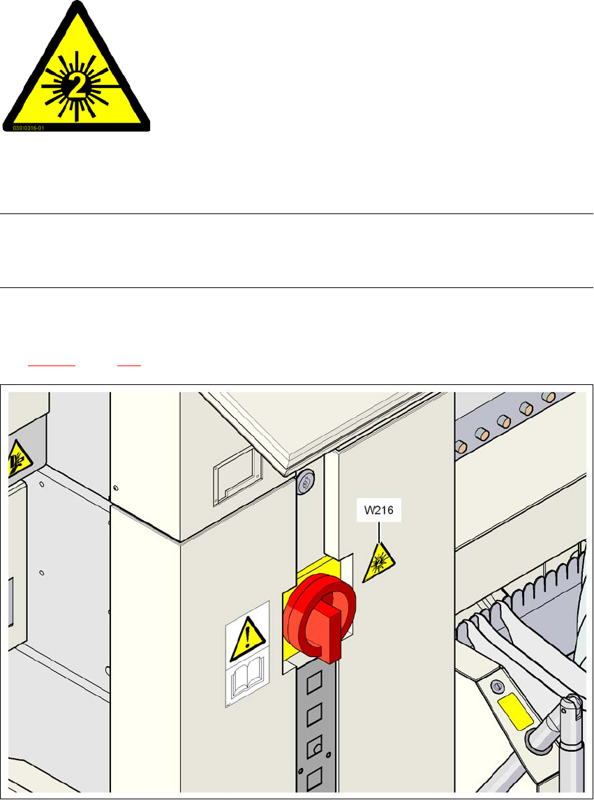
→ Identify the machine with warning sign W216 "Laser class 2", item no. 03010316-xx.
→ Stick warning label W216 beside the main power switch on the cover (see Pos. W216 in Fig.
6.17 - 3
, page 337).
6
Fig. 6.17 - 3 Warning label W216 beside the main switch
6
6
6
6
6
6
LASER RADIATION!
Do not look into beam
Laser class 2

6 Station extensions User Manual SIPLACE D3
6.17 Coplanarity laser module From software version SR.605.xx 07/2008 EN Edition
338
6.17.6 LED displays on the controller
The statuses of the coplanarity module are indicated by LEDs. The LEDs can be found at the bot-
tom of the controller (see item 6 in Fig. 6.17 - 4
, page 339).
LED state Status display
Green Test object in measuring range
Yellow Middle of measuring range
Red
Outside the measuring range,
with low reflection
LED Off Laser switched off
LED Power Status display
LED lights up Supply voltage present
LED avg avg1 avg2
Off Off No averaging
Red Off Averaging 1
Off Red Averaging 2
Red Red Averaging 3