00195760-0102_UM_D3_SR605_EN.pdf - 第228页
4 Setting up and commissioning User Manual SIPLACE D3 4.3 Setting up the machine From software version SR.605.xx 07/2008 EN Edition 228 4.3.12.2 Computer unit - plug-in connectors on the front p anel 4 → Also check the f…
User Manual SIPLACE D3 4 Setting up and commissioning
From software version SR.605.xx 07/2008 EN Edition 4.3 Setting up the machine
227
4
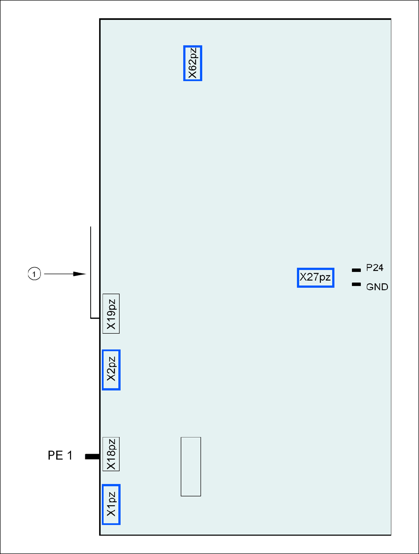
Fig. 4.3 - 19 Computer unit, back panel - Connecting the plugs
(1) Cable guide plate
Fan
Battery
+3.6V

4 Setting up and commissioning User Manual SIPLACE D3
4.3 Setting up the machine From software version SR.605.xx 07/2008 EN Edition
228
4.3.12.2 Computer unit - plug-in connectors on the front panel
4
→ Also check the following plug-in connectors:
4
Computer unit, front
panel
(Fig. 4.3 - 18
, page 226)
Plug
Connecting cable PLEASE NOTE
Plug Cable
X0pr
a
X0pr 03009778 Insert as far as the stop
X1pr
a
X1pr 03009838 Insert as far as the stop
X2pr
a
X2pr 03009755 Insert as far as the stop
X3pr
a
X3pr 03009756 Insert as far as the stop
X8pc X8pc 03002970 Secure with screws
X7pc X7pc 03002967 Secure with screws
X5pc X5pc 03002958 + 03002959 Insert as far as the stop
X7pn X7pn 03010055 Secure with screws
X0ps
a
X0ps 03009798 Insert as far as the stop
X1ps
a
X1ps 03009818 Insert as far as the stop
X2ps
a
X2ps 03009757 Insert as far as the stop
X3ps
a
X3ps 03009758 Insert as far as the stop
a) This plug is intended for cameras.
Computer unit, front
panel
(Fig. 4.3 - 18
, page 226)
Plug
Connecting cable Computer unit, front panel
(Fig. 4.3 - 18
, page 226)
Plug
Plug Cable Plug
X1pe X1pe 03010623 X11pt X11pt
a
X3pe X3pe 03010623 X11pc X11pc
X4pe X4pe 03010623 X11pa X11pa
X1pv X1pv 03010615 X4pa X4pa
X2pv X2pv 03010615 X4pc X4pc
X3pv X3pv 03010619 X4pt X4pt
a
a) Only if vision processor option is installed

User Manual SIPLACE D3 4 Setting up and commissioning
From software version SR.605.xx 07/2008 EN Edition 4.3 Setting up the machine
229
4.3.12.3 Computer unit - plug-in connectors on the back panel
4
4
4.3.12.4 Fitting the computer unit
→ Plug in the plug-in connectors on the back panel of the computer unit (see Section 4.3.12.3).
→ Carefully lift the computer unit onto the rail in the extension kit.
→ Make sure that you do not squash any cables.
→ Check that the cables for the front panel are in the lateral cable routing plate
(item 1 in Fig. 4.3 - 18
, page 226).
→ Fix the cables to the front panel with cable ties.
→ Push the computer unit into the extension kit as far as the stop.
→ Connect the fan cable to the computer unit cable.
→ Plug in the plug-in connectors on the front panel of the computer unit (see Section 4.3 - 16
,
page 222
).
→ Secure the computer unit with the fillister head screw.
→ Fix the grounding cable to the doors (item 2 in Fig. 4.3 - 13
, page 217),
as shown in Fig. 4.3 - 14
on page 220.
→ Lock the doors.
Computer unit,
back panel
(Fig. 4.3 - 19
)
Plug
Connecting cable PLEASE NOTE
Plug Cable
PE1 Cable ring Grounding cable
Fix as shown in Fig. 4.3 - 14
,
page 220
.
X27pz X27pz 03003437 W1-W2 Insert as far as the stop
X2pz X2pz 03002966 W1-W5 Fix with screws
X1pz X1pz 03002969 W1-W5 Fix with screws
X62pz X62pz 03002488 Snap into place
P24 / GND X1 Fan in extension kit Insert as far as the stop