00195760-0102_UM_D3_SR605_EN.pdf - 第139页
User Manual SIPLACE D3 3 Technical data for the machine From software version SR.605.xx 07/2008 EN Edition 3.8 Vision system 139 3.8.6.3 Fiducial criteria 3 3.8.6.4 Ink spot criteria 3 Locate 2 fiduci als Locate 3 fiduci…
3 Technical data for the machine User Manual SIPLACE D3
3.8 Vision system From software version SR.605.xx 07/2008 EN Edition
138
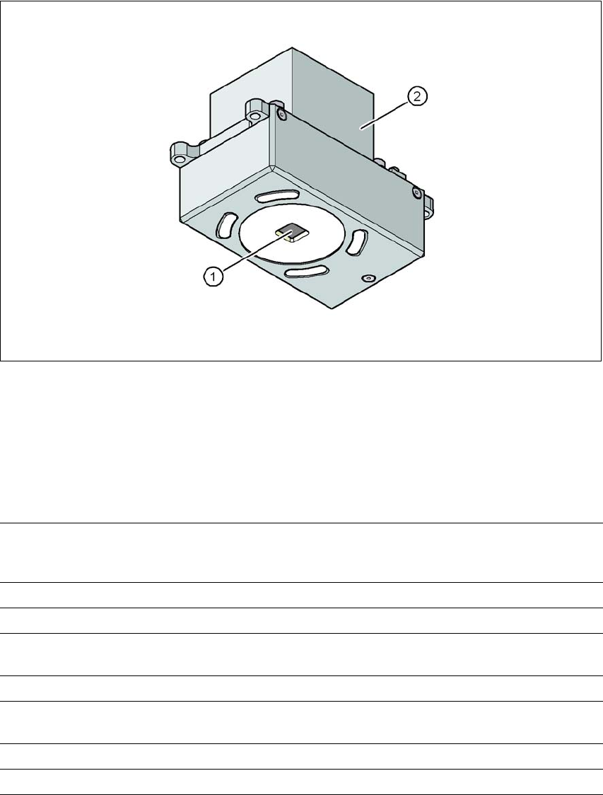
3.8.6 PCB camera, type 34, digital
3.8.6.1 Structure
3
Fig. 3.8 - 5 PCB camera, type 34, digital
(1) PCB camera lens and illumination
(2) Camera amplifier
3.8.6.2 Technical data
3
PCB fiducials Up to 3 (subpanels and multiple panels),
up to 6 for the Long board option (optional PCB fiducials are
output by the optimization).
Local fiducials Up to 2 per PCB (may be of different type)
Library memory Up to 255 fiducial types per subpanel
Image analysis Edge detection method (Singular feature) based on grayscale
values
Method of illumination Front-illumination (3 levels, programmable as required)
Detection time per fiducial
/Bad fiducial
20 ms - 200 ms
Field of vision 5.78 x 5.78 mm²
Distance from the focus plane 28 mm

User Manual SIPLACE D3 3 Technical data for the machine
From software version SR.605.xx 07/2008 EN Edition 3.8 Vision system
139
3.8.6.3 Fiducial criteria
3
3.8.6.4 Ink spot criteria
3
Locate 2 fiducials
Locate 3 fiducials
X-/Y-position, rotation angle, mean PCB distortion
in addition: shear, distortion in X- and Y-direction separately
Fiducial shapes Synthetic fiducials: circle, cross, square, rectangle, rhombus, circular,
square, and rectangular contours, double cross
any pattern
Fiducial surface
Copper
Tin
Without oxidation and solder resist
Warp ≤ 1/10 of structure width, both with good contrast to environment
Dimensions of synthetic fiducials
Min. X/Y size for circle and rectangle:
Min. X/Y size for annulus and rectangle:
Min. X/Y size for cross:
Min. X/Y size for double-cross:
Min. X/Y size for rhombus:
Min. frame width for annulus and rectangle:
Min. bar width / bar distance for cross, double-cross:
Max. X/Y size for all fiducial shapes:
Max. bar width for cross, double-cross:
Min. tolerances, general:
Max. tolerances, general:
0.25 mm
0.3 mm
0.3 mm
0.5 mm
0.35 mm
0.1 mm
0.1 mm
3 mm
1.5 mm
2% of nominal dimension
20% of nominal dimension
Dimensions of patterns
Min. size
Max. size
0.5 mm
3 mm
Fiducial environment Clearance around reference fiducial not necessary if there is no similar
fiducial structure in the search area.
Methods - Synthetic fiducial recognition method
- Mean grayscale value
- Histogram method
- Template matching
Shapes and sizes of fiducials/
structures for
Synthetic fiducials
Other methods
For dimensions of synthetic fiducials, see Section 3.8.6.3
Fiducial
criteria
Min. 0.3 mm
Max. 5 mm
Masking material Good coverage
Recognition time Depends on the method: 20 ms - 0.2s
3 Technical data for the machine User Manual SIPLACE D3
3.9 Feeder modules From software version SR.605.xx 07/2008 EN Edition
140
3.9 Feeder modules
The following feeder modules are currently available to provide the machine with the various com-
ponent types:
3.9.1 Tape feeder modules
– 8 mm SII feeder module
– 3 x 8 mm S feeder module
– 3 x 8 mm S feeder module for 0201/0402 components in paper tape
– 3 x 8 mm S feeder module SL
a
as of 0201 components in paper tape or blister tape
– S feeder module for 12/16 mm, 24/32 mm, 44 mm, 56 mm, 72 mm and 88 mm
– S DP feeder module for deep pockets, 24/32 mm, 44 mm and 56 mm
3.9.2 Other feeder modules
– Linear vibratory feeder, type 3
– Bulk case feeder module
– Surf tape feeder module for 8 mm, 12 mm and 16 mm
– Waffle-pack tray holder
3.9.3 Description
These feeder modules can be used to process all components with the most common package
forms, such as bulk cases, stick magazines and taped components.
The most important feature of the modular component feeding system is its great flexibility. For
example, the conveyor increment can be set on the feeder module. Paper and blister tapes can
be processed with the tape feeder modules. A small range of feeder module types is sufficient to
place a large range of component types.
→ The position detection system on the feeder modules can precisely determine the component
pick-up position. The position detection is carried out automatically whenever the feeder mod-
ule or component trolley is changed.
The feeder modules can be quickly and easily changed or replaced, even by unskilled personnel.
a) SL = shutterless, that is without any component cover