00195760-0102_UM_D3_SR605_EN.pdf - 第130页
3 Technical data for the machine User Manual SIPLACE D3 3.7 PCB conveyor system From software version SR.605.xx 07/2008 EN Edition 130 3.7.6 Configuration options 3.7.6.1 PCB single conveyor Item no. 001 19625-xx D3 modu…
User Manual SIPLACE D3 3 Technical data for the machine
From software version SR.605.xx 07/2008 EN Edition 3.7 PCB conveyor system
129
3.7.5.2 Technical data of the flexible PCB dual conveyor
3
PCB warpage see Section 3.7.7, page 131
PCB weight max. 3 kg
Clearance on PCB underside
Standard
Option
25 mm ± 0.2 mm
max. 40 mm ± 0.2 mm
Component-free PCB handling edge 3 mm
PCB changeover time < 2.5 s
PCB positioning accuracy ± 0.5 mm
PCB conveyor height 830mm ± 15mm (standard)
900mm ± 15mm (optional)
930mm ± 15mm (optional)
950mm ± 15mm (SMEMA: optional)
Type of interface SMEMA / Siemens
Bad fiducial detection possible
Automatic width adjustment possible
a) See Long board option, Section 6.11, page 327
b) With PCB widths > 450 mm make sure that the peripheral modules are also able to process these widths.
Fixed conveyor side Right or left
PCB format
Standard (length x width)
Wide board configuration
Long board option
a
Long board option in
Wide board configuration
Dual conveyor in
Single conveyor mode
Standard (length x width)
Wide board configuration
Long board option
Long board option in
Wide board configuration
50 x 50 mm² to 450 x 216 mm²
50 x 50 mm² to 450 x 250 mm²
50 x 80 mm² to 610 x 216 mm²
50 x 80 mm² to 610 x 250 mm²
50 x 50 mm² to 450 x 380 mm²
50 x 50 mm² to 450 x 450 mm²
50 x 80 mm² to 610 x 380 mm²
50 x 80 mm² to 610 x 450 mm²
PCB thickness
Standard 0.3 mm to 4.5 mm ± 0.2 mm
(thicker PCBs available on request)
PCB warpage see Section 3.7.7
, page 131
PCB weight max. 3 kg
3 Technical data for the machine User Manual SIPLACE D3
3.7 PCB conveyor system From software version SR.605.xx 07/2008 EN Edition
130
3.7.6 Configuration options
3.7.6.1 PCB single conveyor
Item no. 00119625-xx D3 modular single conveyor
Item no. 00119626-xx Stationary conveyor side on the right, HF/X/D-series
Item no. 00119628-xx Stationary conveyor side on the left, HF/X/D-series
Item no. 00119629-xx Conveyor width 250/508 mm (Wide board), X-series/D3
Item no. 00119631-xx Conveyor width 242/508 mm (Wide board), D1/D2/D3/D4
3.7.6.2 Flexible PCB dual conveyor
Item no. 00119627-xx D3 modular dual conveyor
Item no. 00119626-xx Stationary conveyor side on the right, HF/X/D-series
Item no. 00119628-xx Stationary conveyor side on the left, HF/X/D-series
Item no. 00119629-xx Conveyor width 250/508 mm (Wide board), X-series/D3
Item no. 00119631-xx Conveyor width 242/508 mm (Wide board), D1/D2/D3/D4
Clearance on PCB underside
Standard
Option
25 mm ± 0.2 mm
max. 40 mm ± 0.2 mm
PCB conveyor height 830mm ± 15mm (standard)
900mm ± 15mm (optional)
930mm ± 15mm (optional)
950mm ± 15mm (SMEMA: optional)
Type of interface SMEMA / Siemens
Component-free PCB handling edge 3 mm
PCB changeover time < 2.5 s
PCB positioning accuracy ± 0.5 mm
Conveyor mode synchronous or asynchronous (selected via the soft-
ware)
Components on each conveyor same or different
PCB width on each conveyor same or different
Bad fiducial detection synchronous: possible, no global ink spot
asynchronous: possible
Automatic width adjustment synchronous: possible, asynchronous: possible
a) See Long board option, Section 6.11, page 327
User Manual SIPLACE D3 3 Technical data for the machine
From software version SR.605.xx 07/2008 EN Edition 3.7 PCB conveyor system
131
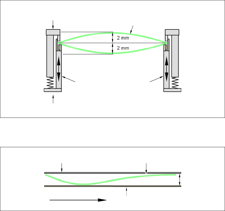
3.7.7 Definition of the PCB warpage
3.7.7.1 PCB warpage on the conveyor
PCB warpage across the direction of travel max. 1% of the PCB diagonal, but not exceeding 2 mm
3
PCB warpage in direction of travel + PCB thickness < 5.5 mm
3
3
Fixed clamped edge
Movable clamping device
Printed circuit board
Conveyor side wall
Fixed clamped edge
Conveyor belt
Printed circuit board
PCB transport direc-
tion
5.5 mm