00195760-0102_UM_D3_SR605_EN.pdf - 第244页
4 Setting up and commissioning User Manual SIPLACE D3 4.3 Setting up the machine From software version SR.605.xx 07/2008 EN Edition 244 4 Fig. 4.3 - 31 Setting the height for the outer machine feet 4 (1) Adjust ing screw…
User Manual SIPLACE D3 4 Setting up and commissioning
From software version SR.605.xx 07/2008 EN Edition 4.3 Setting up the machine
243
4.3.18 Making final adjustments to the machine
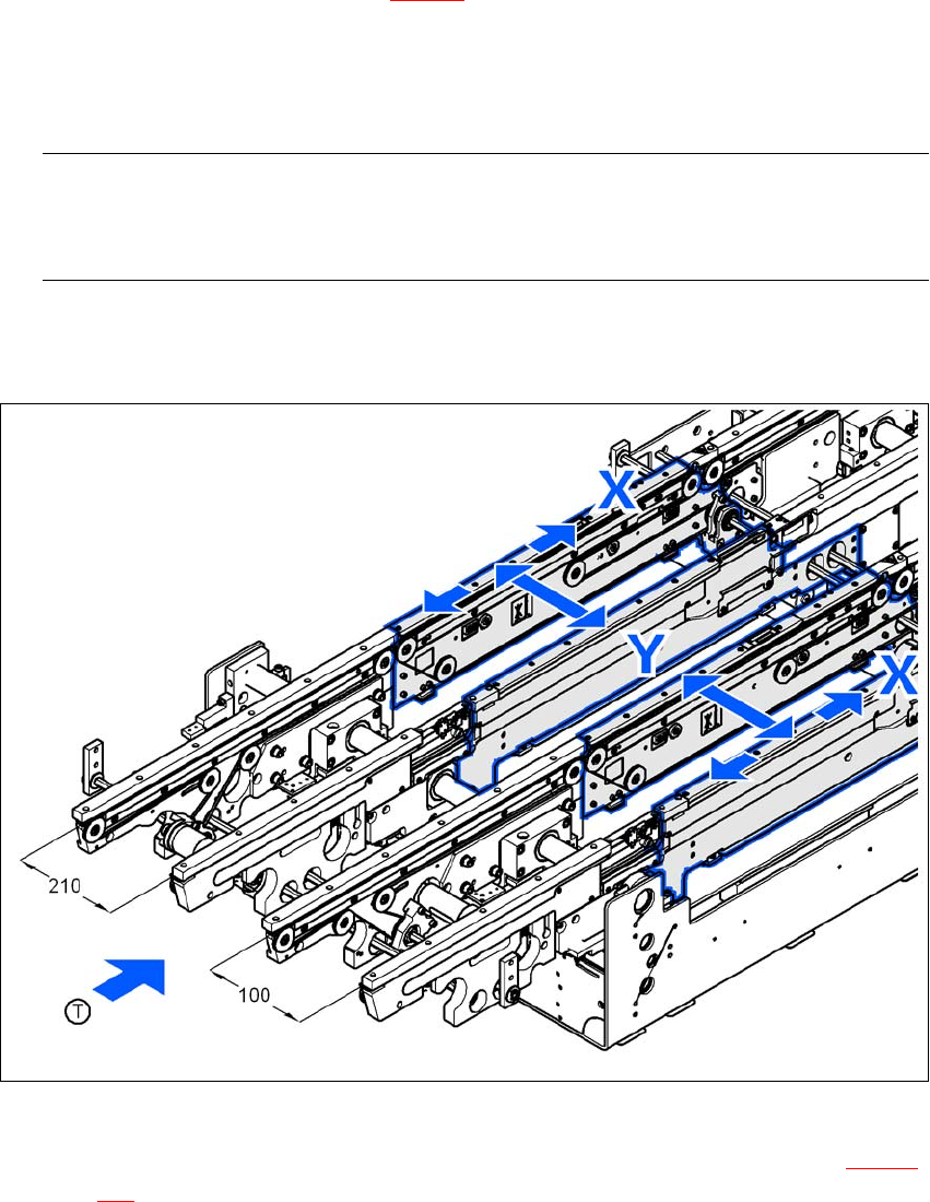
→ Place the machine's spirit level on the rails of the PCB conveyor in placement area 1 in both
the X and the Y directions (see Fig. 4.3 - 30
). The PCB conveyor width is preset:
Single conveyor 210 mm
Dual conveyor, track 1 100 mm
Dual conveyor, track 2 210 mm 4
PLEASE NOTE: 4
On the dual conveyor, place the spirit level only on the outer rails of the machine for adjusting
in the X direction.
→ Measure the distance between the top edge of the PCB conveyor belt and the floor. This dis-
tance should be 800 mm, 900 mm, 930 mm or 950 mm.
4
Fig. 4.3 - 30 Adjusting the machine in the X and Y directions
→ Use the size 36 fork wrench to adjust the adjusting screw M24x2x120 (item 1 in Fig. 4.3 - 31,
page 244
) so that the label on the machine spirit level does not deviate from the zero point
for the required PCB conveyor height.
4 Setting up and commissioning User Manual SIPLACE D3
4.3 Setting up the machine From software version SR.605.xx 07/2008 EN Edition
244
4
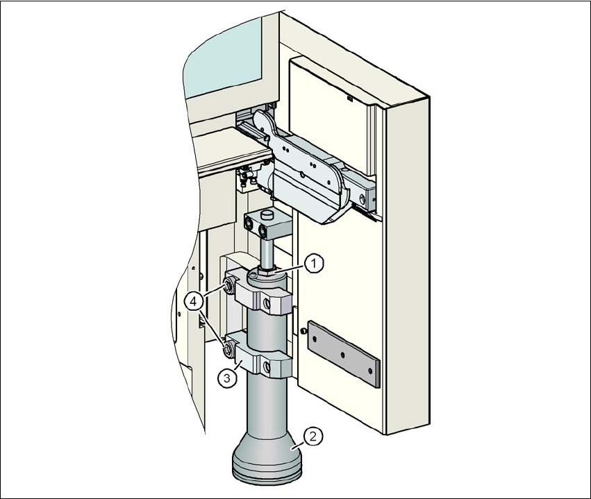
Fig. 4.3 - 31 Setting the height for the outer machine feet
4
(1) Adjusting screw M24x2x120 to adjust the height
(2) Outer machine foot
(3) Clamp
(4) M24x90 hexagon socket head screw
→ Check the required PCB conveyor height.
→ If the machine has been aligned, use the size 19 Allen key to tighten the hexagon socket head
screws M24x90 (item 4) for holding the clamps on all the outer machine feet (item 3).
→ Unscrew the middle machine feet using a hook wrench 135 - 145 until they are seated firmly
on the ground.
→ Make sure that you do not unscrew the middle machine feet so far that the machine is no lon-
ger adjusted.
User Manual SIPLACE D3 4 Setting up and commissioning
From software version SR.605.xx 07/2008 EN Edition 4.3 Setting up the machine
245
4
4
4
4
4
4
4
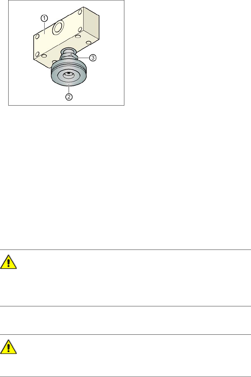
Fig. 4.3 - 32 Aligning and locking the middle machine foot
(1) Spacer
(2) Middle machine foot
(3) M24 lock nut
4
→ Use the spirit level to ensure that the machine is precisely aligned.
→ Use the size 65 open-ended spanner to tighten the M24 lock nut (item 3).
4.3.19 Removing the shipping braces
Remove all the shipping braces from the gantry axes.
4.3.20 Removing the corrosion protection from the guide rails
The machines were given a corrosion protection treatment before they were delivered.
CAUTION 4
– You should therefore remove the corrosion protection from all the axes and bearings when
you traverse the machine axes for the first time during commissioning.
– Grease all the axes and bearings with the grease described in the maintenance instructions.
If the corrosion protection agent is mixed with the bearing grease on the axes this can greatly re-
duce the service life of the bearings and guide rails.
CAUTION 4
Do not allow any alcohol to enter the guide carriages when you clean the guide rails and scale
rods. Alcohol will damage the bearing grease in the guide carriages.