00195760-0102_UM_D3_SR605_EN.pdf - 第163页
User Manual SIPLACE D3 3 Technical data for the machine From software version SR.605.xx 07/2008 EN Edition 3.9 Feeder modules 163 3.9.9.4 Changing the ret ainer → Hold the retainer ( G in Fig. 3.9 - 17 , p age 161 ) firm…
3 Technical data for the machine User Manual SIPLACE D3
3.9 Feeder modules From software version SR.605.xx 07/2008 EN Edition
162
PLEASE NOTE
– The waffle-pack tray holder can only be set up at locations 2 and 4.
– The feeder module positions 14 and 15 on the component table must not be filled.
– The holder and the nozzle changer cannot be used at the same time at location 4.
– The component trolley cannot be docked in/out while the holder is fitted.
→ Insert the front side of the waffle-pack tray holder into the associated centering pin (A in Fig.
3.9 - 17
, page 161).
→ Then position the hole on the rear side of the waffle-pack tray holder onto the centering ball
on the component feeder table (B in Fig. 3.9 - 17
, page 161).
→ Make sure the waffle-pack tray is resting securely on the component table.
→ Position one side of the waffle-pack tray carrier in the mounting (C in Fig. 3.9 - 17
, page 161).
Then press the other side into the mounting (D in Fig. 3.9 - 17
, page 161).
→ Slide the waffle-pack tray up against the stop (E in Fig. 3.9 - 17
, page 161).
→ Secure the waffle-pack tray carrier by pressing the thrust pad (F in Fig. 3.9 - 17
, page 161)
downwards.
→ To remove the waffle-pack tray carrier, press the thrust pad once more.
PLEASE NOTE
Using the holder for small waffle-pack trays (136 mm) a waffle-pack tray (JEDEC or CENELEC
waffle-pack tray) can be fitted directly to the holder, in other words, without a waffle-pack tray car-
rier being used. However, the retainer will require changing (G in Fig. 3.9 - 17, page 161).
WARNING
All locations must be equipped with feeder modules in order to guarantee operational reliability.
If there are not enough feeder modules available, unassigned locations should be fitted with a
hand guard (dummy feeder module). When a waffle-pack holder is set up, the remaining loca-
tions have to be protected again with a hand guard.
User Manual SIPLACE D3 3 Technical data for the machine
From software version SR.605.xx 07/2008 EN Edition 3.9 Feeder modules
163
3.9.9.4 Changing the retainer
→ Hold the retainer (G in Fig. 3.9 - 17, page 161) firmly. Press the thrust pad downwards (F in
Fig. 3.9 - 17
, page 161) and remove the retainer by pressing it out sideways.
3.9.9.5 Data entry
→ Define the waffle-pack trays as described in the SIPLACE Pro operating instructions.
3.9.10 Dip module
Item no. 00117010-xx Dip module for flux and adhesives
3
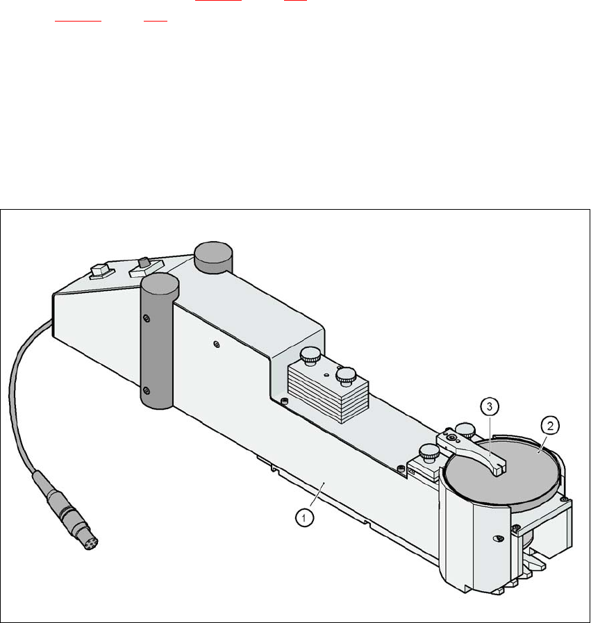
Fig. 3.9 - 18 Dip module
(1) Dip module
(2) Rotating plate
(3) Squeegee

3 Technical data for the machine User Manual SIPLACE D3
3.9 Feeder modules From software version SR.605.xx 07/2008 EN Edition
164
3.9.10.1 Description
The dip module (item 1 in Fig. 3.9 - 18) is used to wet flip-chip and CSP components with flux or
conductive adhesive. The flux holder is a rotating plate (item 2 in Fig. 3.9 - 18
, page 163), on which
a thin film of flux (e.g. 40 μm) is created with a squeegee (item 3 in Fig. 3.9 - 18
, page 163). This
method is particularly suitable for highly viscous (honey-like) fluxes. The amount of flux required
for the process is reduced to a minimum coating thickness since only the undersides of the bumps
have to be wetted.
The Dip module is suitable for all the placement heads. It is regarded as a separate feeder module
type by the set-up optimization. There is no limit to the number of dip modules at the individual
locations.
3.9.10.2 Technical data
Locations filled 3
Component size Max. 36 x 36 mm²
depending on the placement head type
Possible coating thicknesses 25, 35, 45, 55, 65, 75 μm
Time required to change the coating thickness Less than 1 min.
Gap height tolerance ± 5 μm
Time for 1 revolution of the table Can be set using the potentiometer
from 0 - 10 s
Component dip time Programmable from 0 - 2 s
in 0.1 s increments
Flux Highly viscous flux, conductive adhesive
Further technical data and information on programming can be found in the Betriebsanleitung
DIP-Modul / DIP Module User Manual, item no. 00195065-xx.
3