00195760-0102_UM_D3_SR605_EN.pdf - 第121页
User Manual SIPLACE D3 3 Technical data for the machine From software version SR.605.xx 07/2008 EN Edition 3.6 Gantry system 121 3.6.4 Structure of the Y axis 3 Fig. 3.6 - 3 S tructure of the Y axis (1) Y -axis linear mo…

3 Technical data for the machine User Manual SIPLACE D3
3.6 Gantry system From software version SR.605.xx 07/2008 EN Edition
120
The X axis essentially consists of the following main modules:
– Gantry arm (item 1 in Fig. 3.6 - 2
, page 119)
– Head mount with X-axis linear motor (primary part) (item 2 in Fig. 3.6 - 2
, page 119)
– Linear distance measuring system (item 3 in Fig. 3.6 - 2
, page 119)
– Guide system (item 4 in Fig. 3.6 - 2
, page 119)
– Permanent magnet (secondary part of the X-axis linear motor) (item 5 in Fig. 3.6 - 2
, page
119
)
– Cable and hose carrier (item 8 in Fig. 3.6 - 2
, page 119)
3
The head mount (2) holds the following components:
– Sub-gantry camera (PCB camera for the PCB vision module) (item 6 in Fig. 3.6 - 2
, page
119
)
– Set of head boards (item 7 in Fig. 3.6 - 2
, page 119)
– Measuring head for the measuring system
– Collect&Place head or SIPLACE TwinHead
The gantry arm (item 1 in Fig. 3.6 - 2
, page 119) is produced from a carbon fiber composite ma-
terial. which makes the modules extremely light while, at the same time, being very rigid.
The X axis is driven by a linear motor. The secondary part of the drive consists of a permanent
magnet and is mounted on the gantry arm. The primary part is bolted to the head mount. The head
mount was designed to take all types of placement head - another indicator of the high level of
flexibility that can be achieved with SIPLACE machines.
3.6.3 Technical data for the X axis
3
Drive Direct, linear motor
Maximum speed 2.5 m/sec.
Traversing path 480 mm
Distance measuring system Metal linear scale
Scale length 520 mm
Resolution 1 μm
User Manual SIPLACE D3 3 Technical data for the machine
From software version SR.605.xx 07/2008 EN Edition 3.6 Gantry system
121
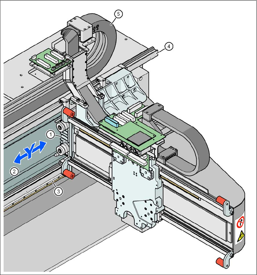
3.6.4 Structure of the Y axis
3
Fig. 3.6 - 3 Structure of the Y axis
(1) Y-axis linear motor (primary part)
(2) Permanent magnet (secondary part of the Y-axis linear motor)
(3) Linear distance measuring system
(4) Guide system
(5) Cable and hose carrier

3 Technical data for the machine User Manual SIPLACE D3
3.6 Gantry system From software version SR.605.xx 07/2008 EN Edition
122
The Y axis essentially consists of the following main modules:
– Y-axis linear motor (primary part) (item 1 in Fig. 3.6 - 3
, page 121)
– Permanent magnet (secondary part of the Y-axis linear motor) (item 2 in Fig. 3.6 - 3
, page
121
)
– Linear distance measuring system (item 3 in Fig. 3.6 - 3
, page 121)
– Guide system (item 4 in Fig. 3.6 - 3
, page 121)
– Cable and hose carrier (item 5 in Fig. 3.6 - 3
, page 121)
The Y axis is driven by a linear motor. The secondary part of the drive is made up of permanent
magnets and is mounted on the machine frame. The primary part is bolted to the gantry.
3.6.5 Technical data for the Y axis
Drive Direct, linear motor
Maximum speed 2.5 m/sec.
Traversing path 1430 mm
Distance measuring system Metal linear scale
Scale length 1850 mm
Resolution 1 μm