00195760-0102_UM_D3_SR605_EN.pdf - 第234页
4 Setting up and commissioning User Manual SIPLACE D3 4.3 Setting up the machine From software version SR.605.xx 07/2008 EN Edition 234 4.3.16 Machine foot clearances and the st ationary PCB conveyor edges 4.3.16.1 Machi…
User Manual SIPLACE D3 4 Setting up and commissioning
From software version SR.605.xx 07/2008 EN Edition 4.3 Setting up the machine
233
4
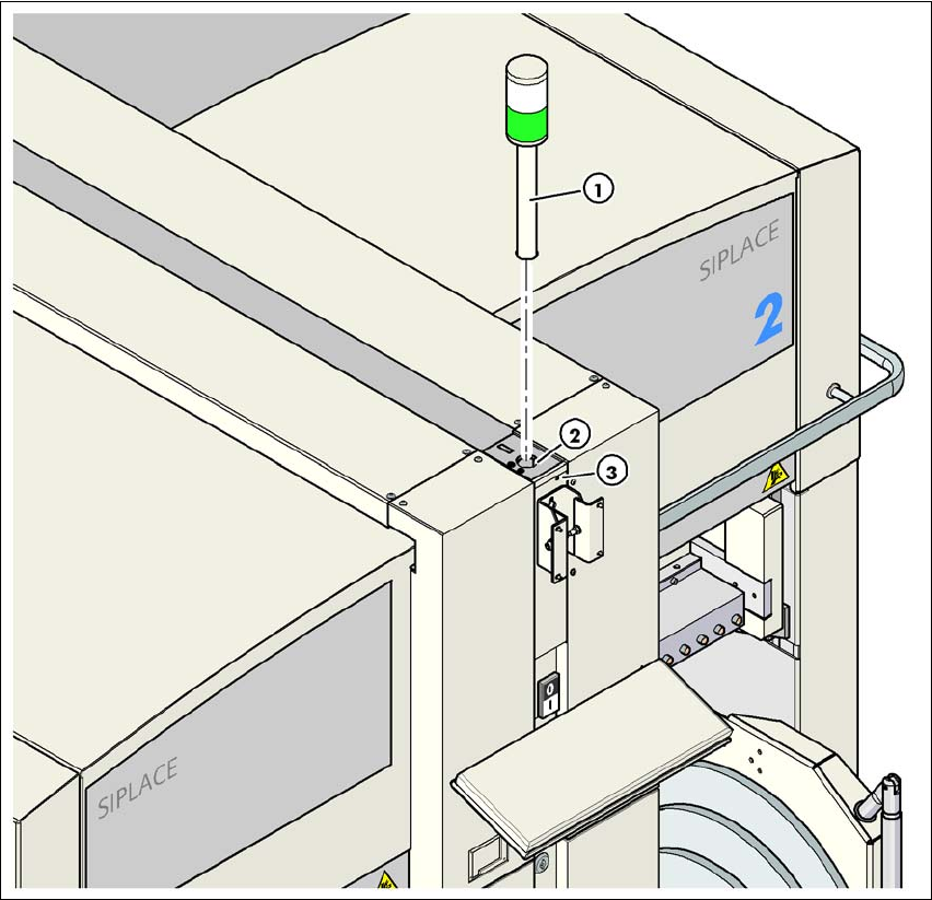
Fig. 4.3 - 21 Fitting the indicator lamp
(1) Indicator lamp
(2) Hole for the indicator lamp
(3) Hole for the locking screw
4.3.15 Fixing the monitors
→ Fix the monitors and connect the cables.
→ Check the cable connections
4 Setting up and commissioning User Manual SIPLACE D3
4.3 Setting up the machine From software version SR.605.xx 07/2008 EN Edition
234
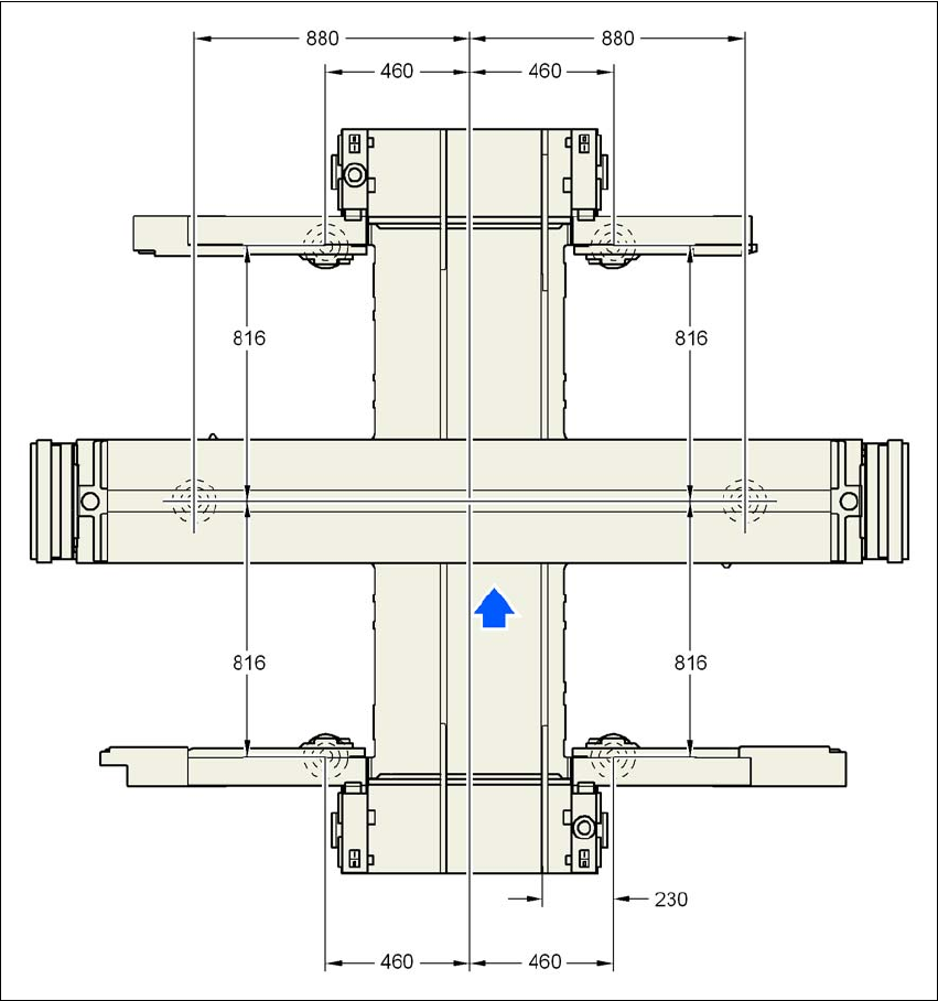
4.3.16 Machine foot clearances and the stationary PCB conveyor edges
4.3.16.1 Machine foot clearances and the stationary right conveyor edge for the
PCB single conveyor
4
Fig. 4.3 - 22 Machine foot clearances and the stationary right conveyor edge for the PCB single conveyorin millime-
ters
User Manual SIPLACE D3 4 Setting up and commissioning
From software version SR.605.xx 07/2008 EN Edition 4.3 Setting up the machine
235
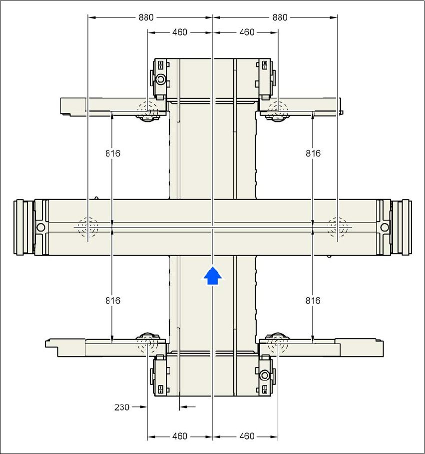
4.3.16.2 Machine foot clearances and the stationary left conveyor edge for the
PCB single conveyor
4
Fig. 4.3 - 23 Machine foot clearances and the stationary left conveyor edge for the PCB single conveyor in millimeters