00195760-0102_UM_D3_SR605_EN.pdf - 第322页
6 Station extensions User Manual SIPLACE D3 6.7 PCB barcode scanner From software version SR.605.xx 07/2008 EN Edition 322 6.7.6.2 Positioning along the long side of the PCB - Scanning beam along the direction of travel …
User Manual SIPLACE D3 6 Station extensions
From software version SR.605.xx 07/2008 EN Edition 6.7 PCB barcode scanner
321
6.7.5 Warning label W216 on the cover of the PCB input side
6
Warning label W216 "Laser class 2" on the cover of the PCB input side,
item no. 03010316-01 (number per machine: 1)
PLEASE NOTE 6
When you install a PCB barcode scanner on the machine, you must attach laser warning label
W206 contained in the retrofit kit to the cover on the PCB input side.
6
6.7.6 Positioning PCB barcode labels on the PCB
PLEASE NOTE 6
Restrictions for PCBs longer than 430 mm
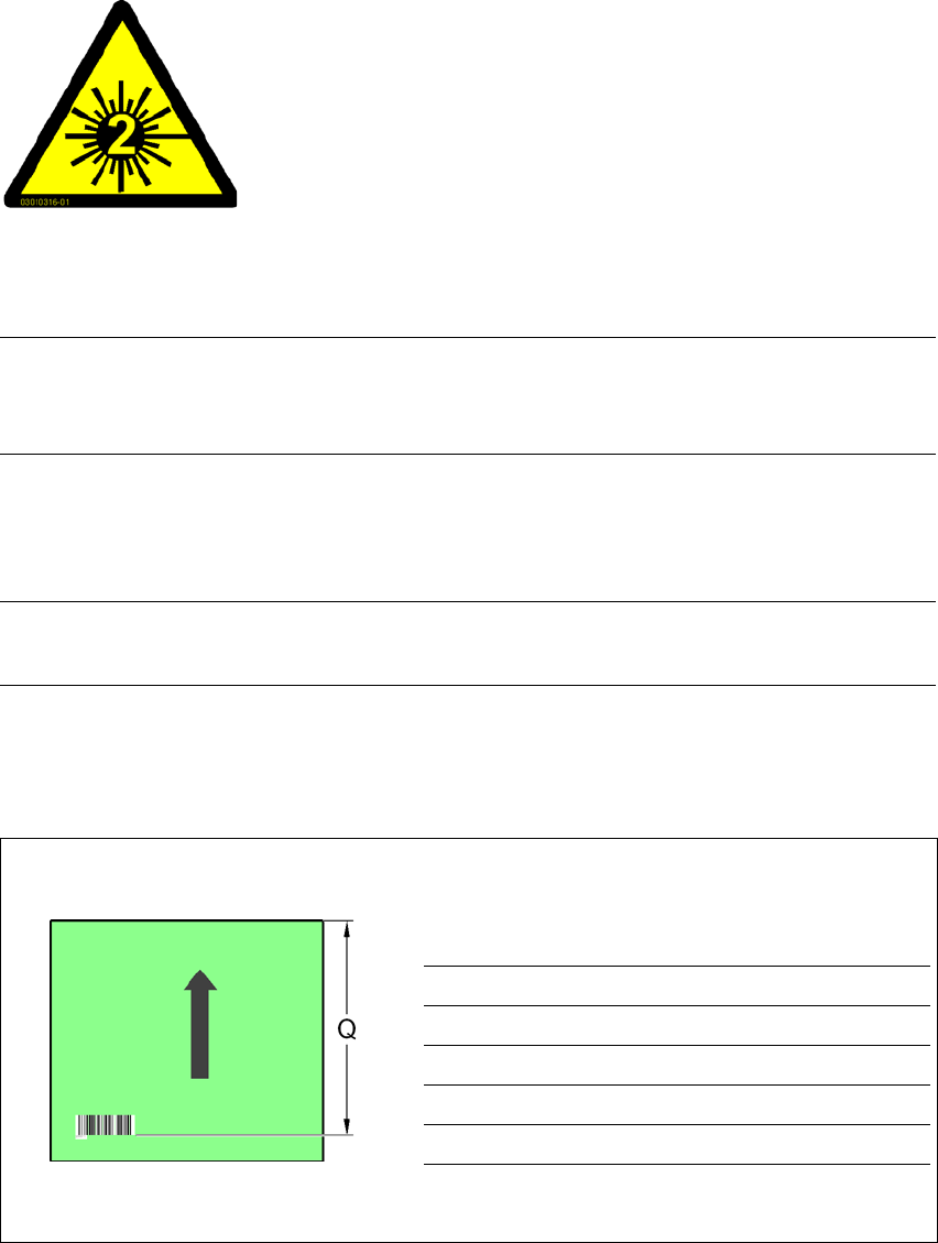
6.7.6.1 Positioning along the long side of the PCB -
Scanning beam across the direction of travel
Fig. 6.7 - 4 Positioning along the long side of the PCB - Scanning beam across the direction of travel
6
6
6
6
6
6
LASER RADIATION!
Do not look into beam
Laser class 2
PCB barcode scanner Q [mm]
2D topside 390
1D topside 390
2D underside 430
1D underside 430
6 Station extensions User Manual SIPLACE D3
6.7 PCB barcode scanner From software version SR.605.xx 07/2008 EN Edition
322
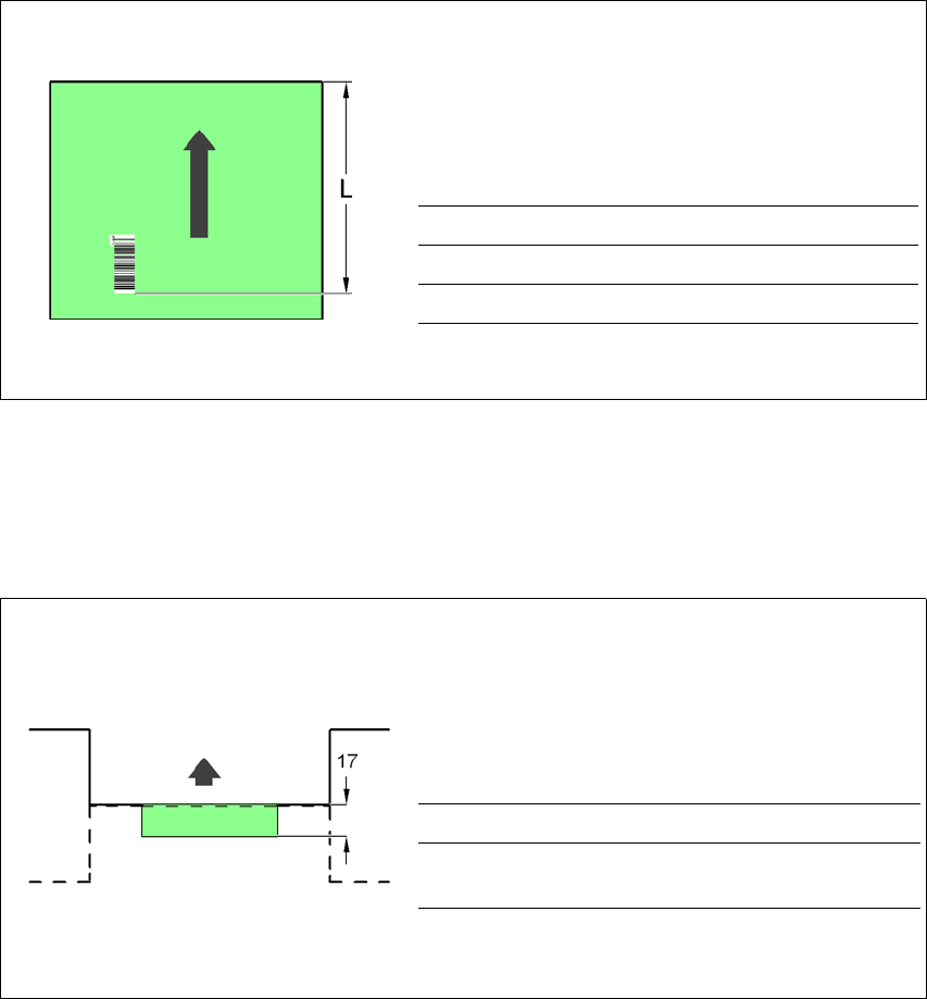
6.7.6.2 Positioning along the long side of the PCB -
Scanning beam along the direction of travel
Fig. 6.7 - 5 Positioning along the long side of the PCB - Scanning beam along the direction of travel
6.7.6.3 PCB overshoot over the machine with the dual conveyor
Fig. 6.7 - 6 PCB overshoot over the machine with the dual conveyor
PCB barcode scanner L [mm]
1D topside 320 - 350
1D underside 380 - 410
PCB barcode scanner Overshoot [mm]
2D underside on the
dual conveyor
17
Input side of the downstream machine
Output side of the upstream machine
User Manual SIPLACE D3 6 Station extensions
From software version SR.605.xx 07/2008 EN Edition 6.7 PCB barcode scanner
323
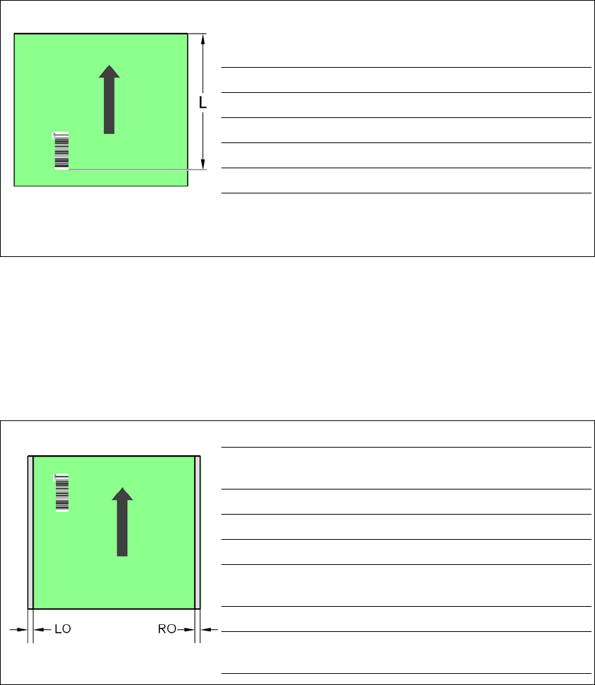
6.7.6.4 Positioning along the width of the PCB -
Scanning beam across the direction of travel
Fig. 6.7 - 7 Positioning along the width of the PCB - Scanning beam across the direction of travel
6.7.6.5 Positioning along the width of the PCB -
Scanning beam along the direction of travel,
PCB barcode scanner 1D topside
Fig. 6.7 - 8 Positioning along the width of the PCB - Scanning beam along the direction of travel
PCB barcode scanner 1D topside
PCB barcode scanner LQ [mm] RQ [mm]
2D topside 3 3
1D topside 3 3
2D underside 5 5
1D underside 5 5
PCB dimensions/convey-
or
LO [mm] RO [mm]
460 mm / SC 3 20
508 mm / SC 3 44
216 mm / DC1 3 24
250 mm / DC1
450 mm / SM1
358
216 mm / DC2 3 3
250 mm / DC2
450 mm / SM2
33