MEC-CP842-1.0E.pdf - 第143页
Adjustments >> Station Adjustments MEC-CP842-1.0E 7-7 Caution:Do not disassemble nozzl e shaf t assemblies care lessly . Special equ ipment and skills are required to remove and reassemble a nozzle shaft. Such proc…
Adjustments >> Station Adjustments
7-6 MEC-CP842-1.0E
7.1.3 Nozzle Vertical Movement During Pickup
(ST1)
Slider Adjustment
Adjust the height of the slider to ensure that the cam follower can travel smoothly
through the slider and along the cam groove.
1 Press the EMERGENCY STOP button. This turns off the 200V power.
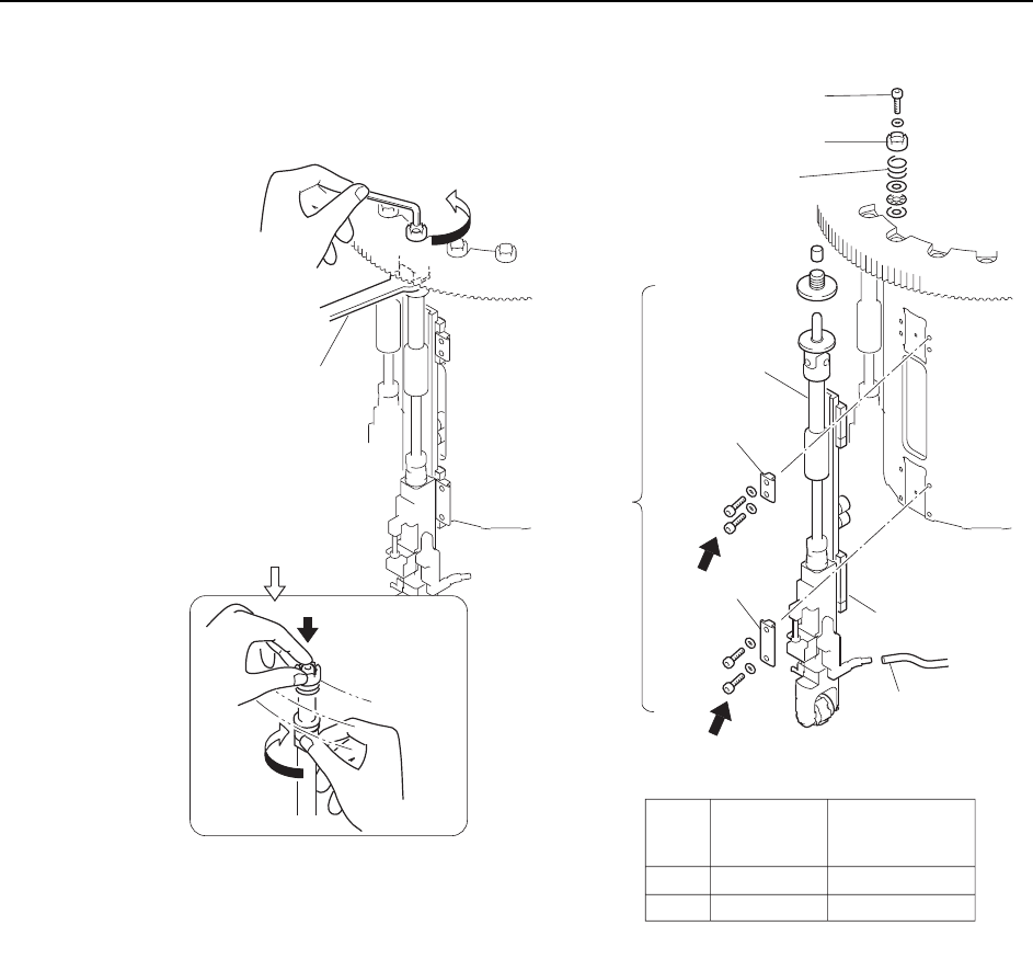
2 In order to remove the nozzle shaft assembly, it is first necessary to remove the
upper clutch. Set the cam angle to 0° (nozzle shaft between ST9 and ST10) and
hold the shaft with a wrench (DCPJ0450) while loosening the Allen bolt. Turn
the loosened bolt by hand and then remove the clutch. (See illustration on the
next page.)
Caution:Remove the G or O nozzle shaft assemblies, because the turret slots are wider for these 2
shafts. Some maintenance is much more difficult with other turret slots.
3 Remove the linear guide clampers and vacuum hose, then remove the nozzle
shaft assembly.
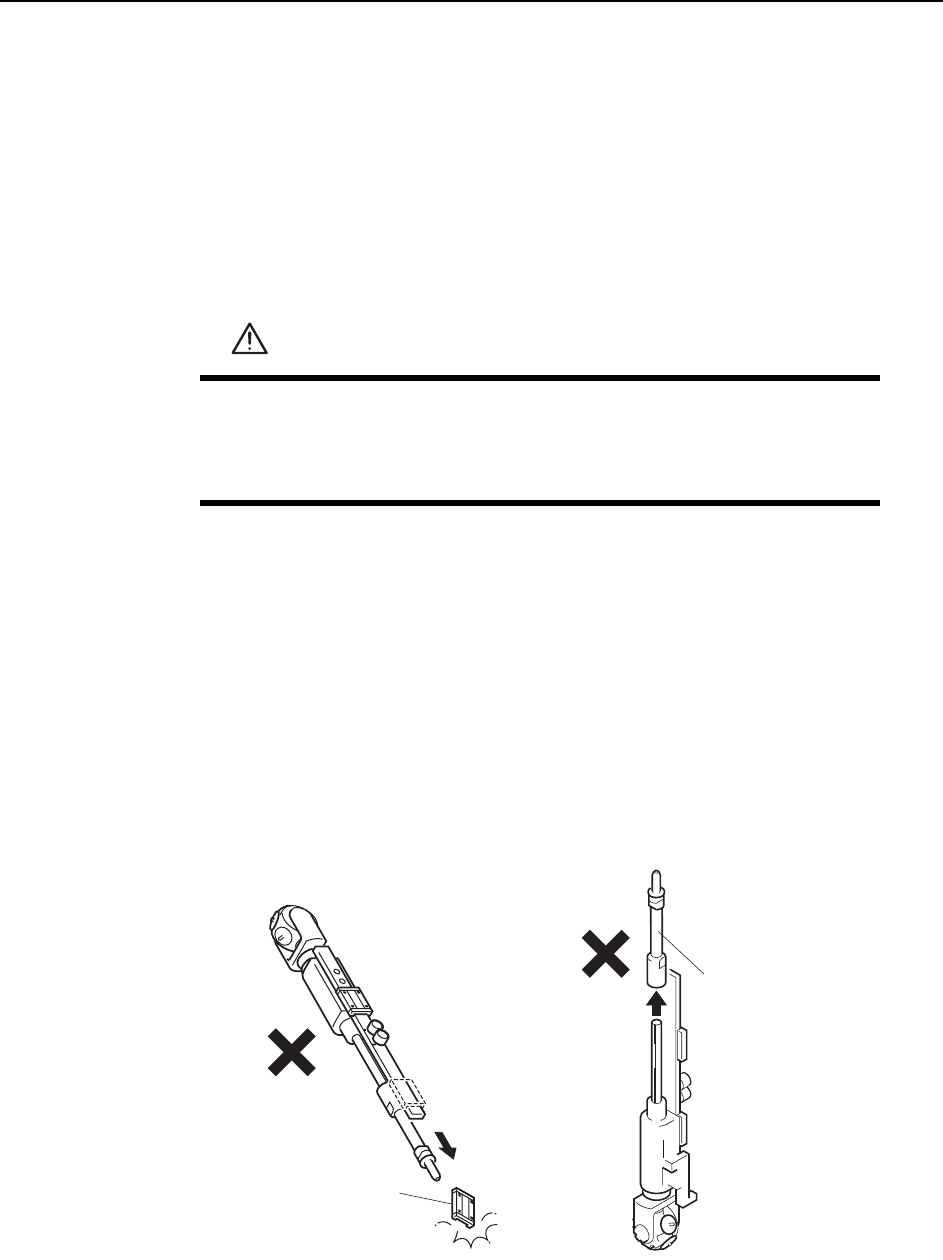
Caution:When handling the nozzle shaft assembly exercise caution to ensure that the linear guide
and outer shaft do not slide off the end of the shaft.
WARNING
• Press EMERGENCY STOP before performing this procedure.
• Exercise extreme caution when working on the machine if the cam
is not at its origin (0 deg.). Spring recoil can rotate the cam inde-
pendently.
Outer shaft
C7SM4011a
Linear guide
Adjustments >> Station Adjustments
MEC-CP842-1.0E 7-7
Caution:Do not disassemble nozzle shaft assemblies carelessly. Special equipment and skills are
required to remove and reassemble a nozzle shaft. Such procedures should be attempted
only by maintenance staff who have attended training at Fuji and are equipped with the nec-
essary tools.
Outer
shaft
Clamper
Wrench
( DCPJ0450 )
Clutch
Bolt
Spring
Linear guide
Vacuum hose
A
B
Part
Bolt
size
Torque
Nm ( Kgf/cm )
A
B
M4
M4
2 ( 20 )
2 ( 20 )
Clamper
C7SM4012a
Nozzle
shaft
assembly
Caution : Washers may move when the
bolt is loosened because of the
spring under the clutch.
Rotate the placing
head while holding
the bolt with finger.
Adjustments >> Station Adjustments
7-8 MEC-CP842-1.0E
4 Move the turret slot for the removed nozzle shaft to ST1, then turn on the sole-
noid Y031 ST1 PICKUP SOL ENGAGED.
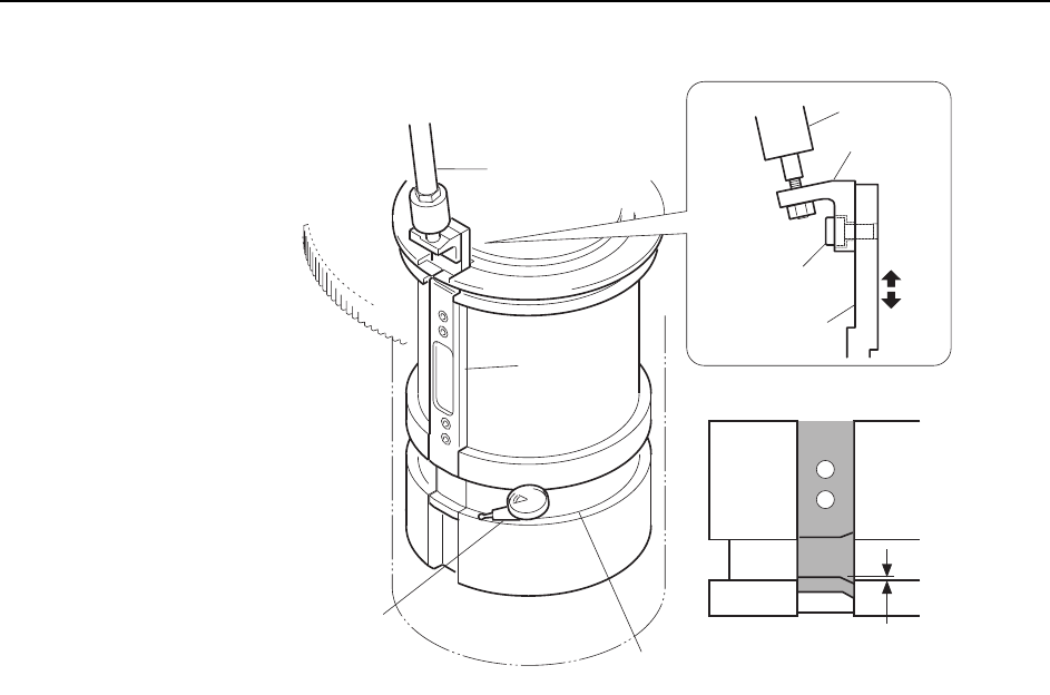
5 Set the cam angle to 0°, and position the dial gauge as shown in the figure
above.
6 Check that the vertical difference between the groove on the slider and the tur-
ret groove is 0 to 0.02 mm. If this range is exceeded, loosen the bolt on the rod
bracket and make the required adjustments to the height of the slider.
7 Tighten the bolt while maintaining the height of the slider.
8 Check the distance between the cam grooves again.
Note: If the alignment of the grooves cannot be adjusted to the correct range, then adjust the height
of the rod that controls the vertical movement of the bracket.
9 Reattach the nozzle shaft assembly in the original location. Reverse the
removal procedures and use the clutch alignment jig to reattach the shaft.
Caution:The nozzle shaft assembly is exclusive to the CP-842E/842ME and cannot be used on other
machine types, such as CP-733E, CP-743ME, or CP-743E.
Slider
Rod
0~0.02 mm
C7SM4013b
Dial gauge
Rod
Bracket
Bolt
Slider
Cam groove