MEC-CP842-1.0E.pdf - 第146页
Adjustments >> Station Adjustme nts 7-10 MEC-CP842-1.0E Adjusting the Nozzle UP Limit Sensor The sensor that detects the height of th e nozzle UP/DOWN rod is mounted inside the cam box. Adjust the sensor ’ s mounti…
Adjustments >> Station Adjustments
MEC-CP842-1.0E 7-9
Confirming the Pick-up Height
Ensure that the nozzle descends low enough to pick up a part set in the feeder. Con-
firm that the mechanical valve movement switches on the vacuum for part pick-up.
1 Set a W8 x P4 mm feeder (with tape leaf removed) at the D1 position.
2 Move the feeder to ST1 by pressing [Position] - (Position) [D1-axis] - enter [1] -
[OK] - START.
3 Check that the NZ-axis is stopping at the position specified at the "PICK UP
POS. NZ" item in Proper data.
4 Push the EMERGENCY STOP button, which disables the 200V power but
leaves the 100V power on.
5 Set the cam angle to 0°, then turn the first nozzle solenoid valve on to activate
the cam lever.
6 Use the cam handle to rotate the cam to 170°.
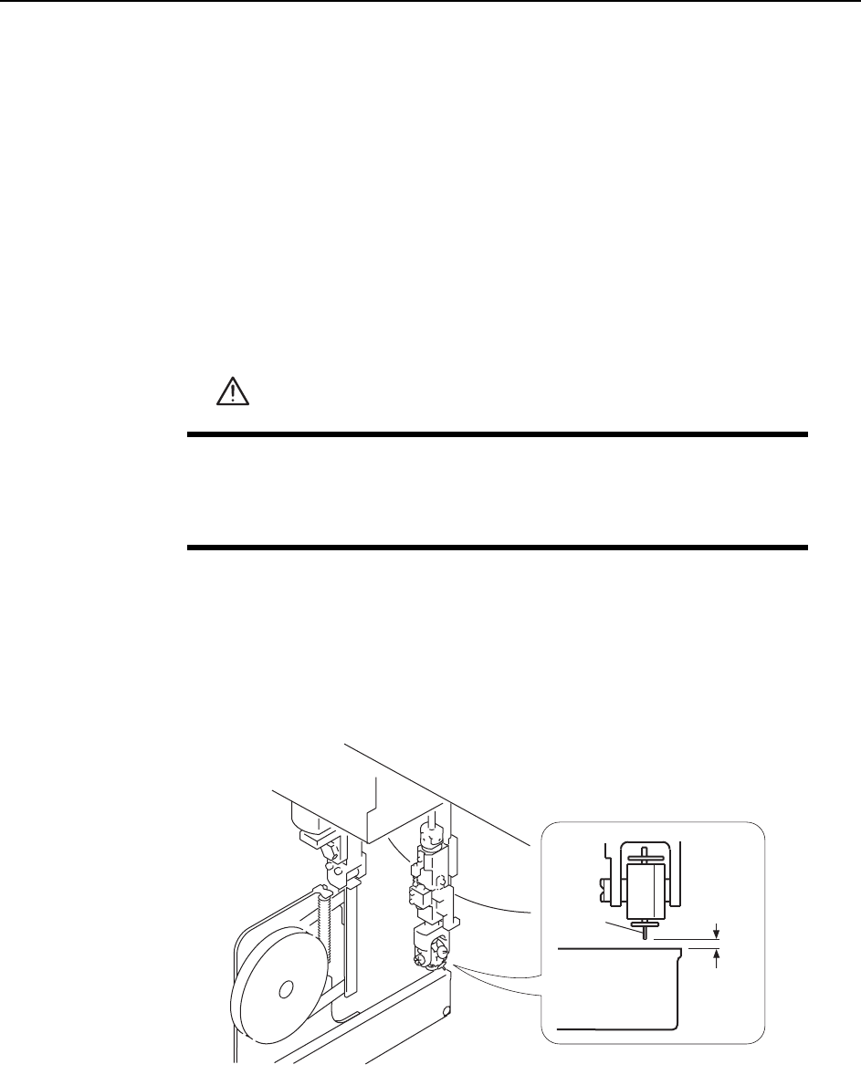
7 Ensure a space of 0.65 mm between the tip of the nozzle and the feeder (pick-up
height).
WARNING
• Press EMERGENCY STOP before performing this procedure.
• Exercise extreme caution when working on the machine if the cam
is not at its origin (0 deg.). Spring recoil can rotate the cam inde-
pendently.
0.65 mm
Feeder
Nozzle
C7SM4014
Adjustments >> Station Adjustments
7-10 MEC-CP842-1.0E
Adjusting the Nozzle UP Limit Sensor
The sensor that detects the height of the nozzle UP/DOWN rod is mounted inside the
cam box. Adjust the sensor’s mounting position so that the sensor switches ON when
the nozzle is at its UP limit.
1 Press the EMERGENCY STOP button. This turns off the 200V power.
2 Set the cam axis at 0°.
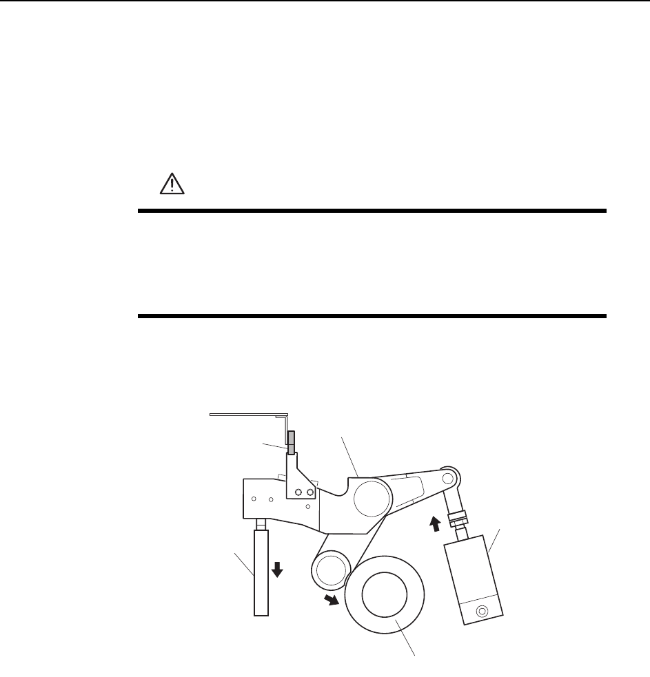
3 Activate the ST1 pick-up solenoid air cylinder (located in the cam box):
WARNING
• Press EMERGENCY STOP before performing this procedure.
• Exercise extreme caution when working on the machine if the cam
is not at its origin (0 deg.). Spring recoil can rotate the cam inde-
pendently.
1ST Pick-up solenoid
air cylinder
Cam lever
Nozzle up limit sensor
Nozzle UP/DOWN
rod
Cam axis
Cam lever follows the cam axis.
C7SM4015a
Adjustments >> Station Adjustments
MEC-CP842-1.0E 7-11
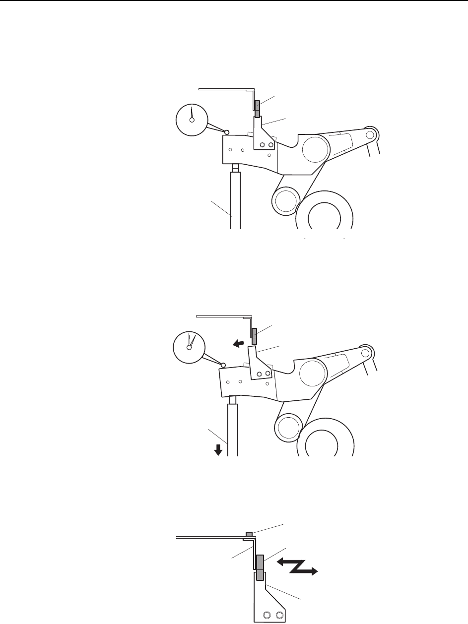
4 Place a dial gauge on the top end of the cam lever and set the gauge reading to
“0”. In this condition, the cam axis will be at 0°, and the nozzle UP/DOWN rod
will be at its UP limit position. Verify that the nozzle UP limit sensor is ON
(X030 ST1 CYLINDER UPPER-LIMIT is ON) at the I/O screen.
5 While observing the dial gauge, rotate the cam axis in the forward direction to
lower the nozzle UP/DOWN rod. Adjust the sensor’s mounting position so that
the sensor switches OFF (X030 ST1 CYLINDER UPPER-LIMIT switches OFF)
when the rod has been lowered 0.3 to 0.4 mm.
6 Adjust the sensor’s mounting position by loosening the sensor lock screw and
sliding the sensor in the front/back directions.
C7SM4016
Dog
Nozzle UP/DOWN
rod
Set the dial gauge
to "0"
Nozzle up limit sensor (ON)
Dog
Nozzle UP/DOWN
rod
Nozzle up limit sensor (OFF)
C7SM4017
C7SM4018a
Nozzle up limit sensor
Screw
Sensor bracket
Dog