MEC-CP842-1.0E.pdf - 第174页
Adjustments >> Station Adjustme nts 7-38 MEC-CP842-1.0E Clutch Meshing Check Sens or Position Adjustment 1 Press the EMERGENCY STOP button to take the 200V down to 100V . 2 Use the cam handle to ro tate the cam to …
Adjustments >> Station Adjustments
MEC-CP842-1.0E 7-37
7.1.11 Reverse-theta Mechanism (ST10)
Point
This mechanism reverses the nozzle rotation to the placement angle, which occurred
at stations 2 and 8.
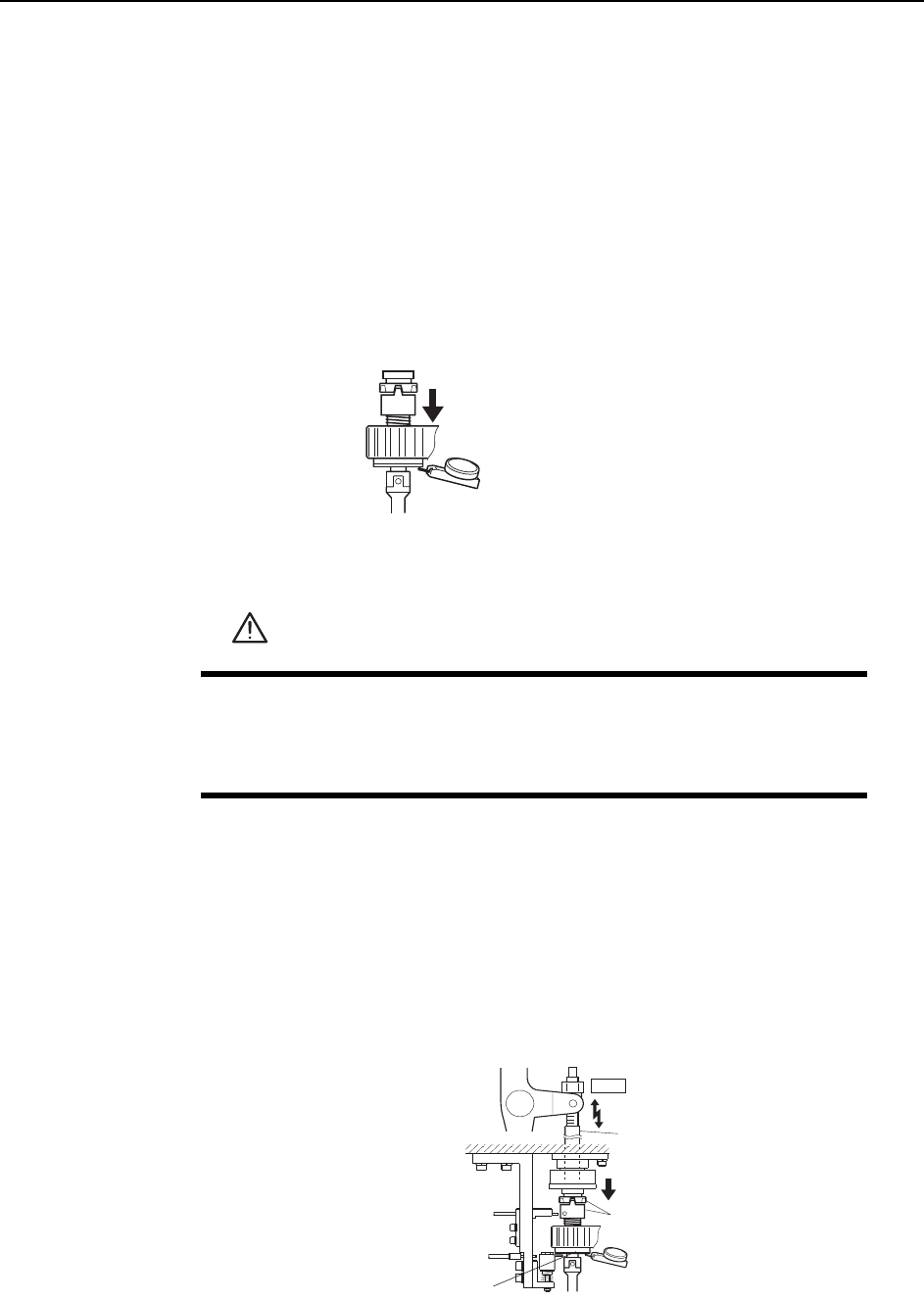
Clutch Meshing Check
Perform this check on the LOW nozzle.
Note: The LOW nozzle refers to the nozzle shaft with the shortest vertical stroke when pushed
down by the clutch. Use the LOW nozzle for checking the stroke at stations 2, 8 and 10.
1 Press the EMERGENCY STOP button to take the 200V down to 100V.
2 Set the cam angle to 0° and turn on the ST10 solenoid valve. The nozzle shaft
should descend when the cam is advanced.
3 Zero the dial gauge on the bottom of the nozzle shaft brake when there is no con-
tact between the clutches.
4 Use the cam handle to rotate the cam to 200°.
5 Ensure that the clutches mesh properly and that the nozzle shaft deflects the
dial gauge 0.30 ~ 0.35 mm, as illustrated below.
WARNING
• Press EMERGENCY STOP before performing this procedure.
• Exercise extreme caution when working on the machine if the cam
is not at its origin (0 deg.). Spring recoil can rotate the cam inde-
pendently.
Measure the vertical stroke
at all nozzles to determine the
lowest value.
C7SM4058
Clutch
ST10
Rod
0.30~0.35 mm
C7SM4038a
Measure the
vertical stroke
Nozzle shaft brake
Adjustments >> Station Adjustments
7-38 MEC-CP842-1.0E
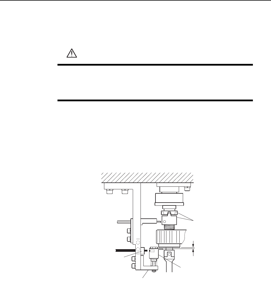
Clutch Meshing Check Sensor Position Adjustment
1 Press the EMERGENCY STOP button to take the 200V down to 100V.
2 Use the cam handle to rotate the cam to 200°.
3 Use the inching keys to align the RQ-axis with the RQ-data position.
4 Make sure the clutches engage properly. Adjust the height of Bracket A so that
Gap C in the figure is 0.2 mm.
5 At this position, adjust the position of Bracket B so that the sensor beam enters
the hole on the dog.
WARNING
• Press EMERGENCY STOP before performing this procedure.
• Exercise extreme caution when working on the machine if the cam
is not at its origin (0 deg.). Spring recoil can rotate the cam inde-
pendently.
Dog
Clutch
Bracket A
Bracket B
C7SM4039a
0.2 mm
C
Adjustments >> Station Adjustments
MEC-CP842-1.0E 7-39
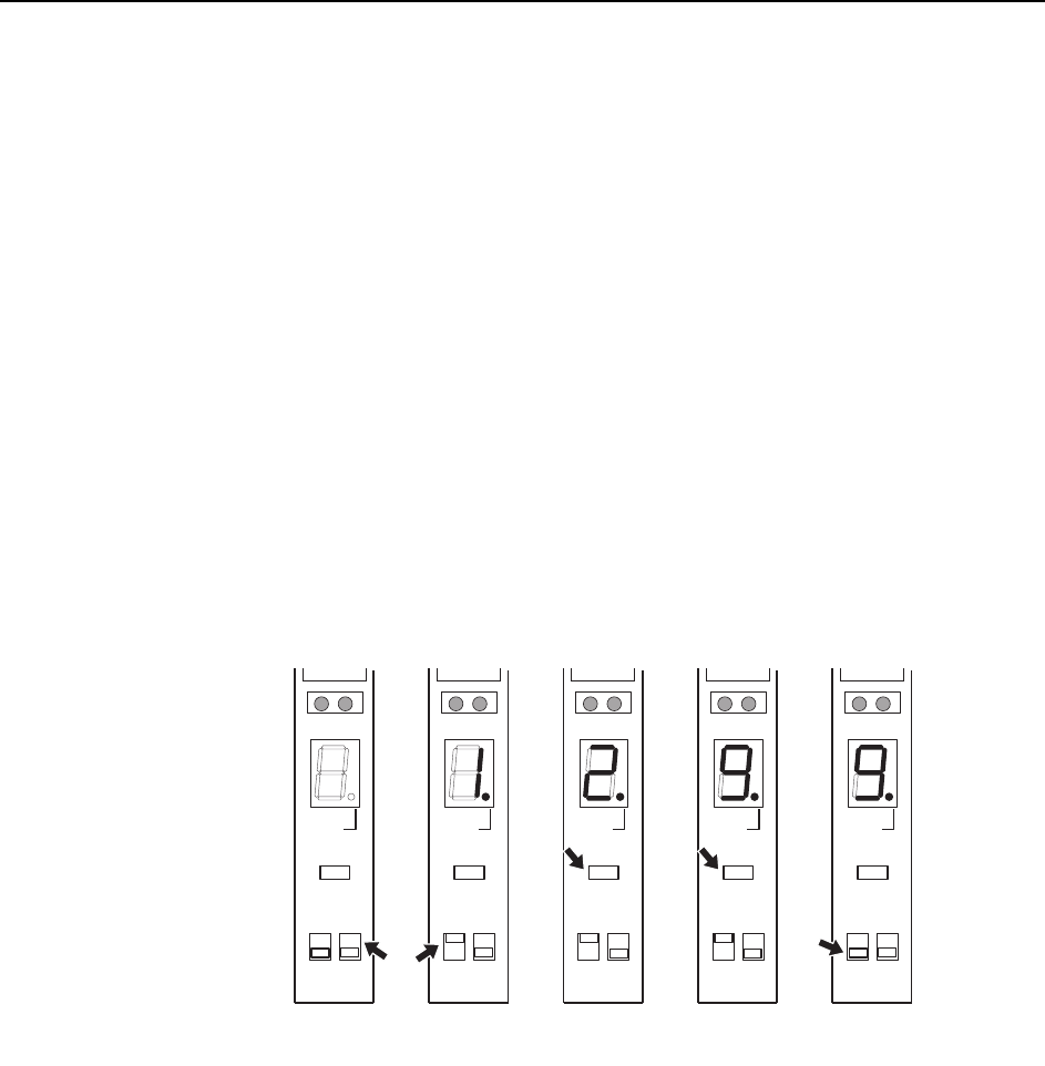
Clutch Meshing Check Sensor Amp Adjustment
Adjust the sensor amplifier so that it switches off when the clutches mesh properly
and on when the clutches do not mesh properly, pushing the sensor dog down.
Remove the cover of the amplifier and follow the procedure below.
Note: Be careful not to drop the cover inside the machine.
1 Set the bottom right switch to “L ON”.
2 Set the mode selector switch to “SET”. The digital display will then indicate “1”.
3 With the clutch engagement sensor on (sensor is detecting the hole in the dog),
press the [TUNING] button. The digital display will then indicate “2”.
4 With the clutch engagement sensor off (sensor is not detecting the hole in the
dog), press the [TUNING] button. The digital display will then indicate “9”.
5 Set the mode selector switch to “RUN”.
6 After completing the amplifier setting procedure, verify that the digital display
indicates 0 ~ 1 when the sensor is on, and 8 ~ 9 at all other times.
( 1 )
C7SM4040
SO
DELAY
TUNING
SET D ON
RUN L ON
( 2 )
SO
DELAY
TUNING
SET D ON
RUN L ON
( 3 )
SO
DELAY
TUNING
SET D ON
RUN L ON
( 4 )
SO
DELAY
TUNING
SET D ON
RUN L ON
( 5 )
SO
DELAY
TUNING
SET D ON
RUN L ON
Sensor ON Sensor OFF