MEC-CP842-1.0E.pdf - 第190页
Adjustments >> Servo Amplifier Adjustments 7-54 MEC-CP842-1.0E 7.2.2 Resetting servo errors Servo errors that cannot be reset using commands at the ma chine can be reset by con- necting the digital operator to the …
Adjustments >> Servo Amplifier Adjustments
MEC-CP842-1.0E 7-53
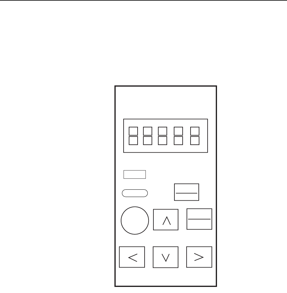
2 Press the [DSPL/SET] button on the Digital Operator until “PN-00” is displayed
by the LED indicator.
3 The parameter type can be changed by pressing the Up or Down arrow key.
4 When the desired parameter is displayed, press the [DATA/ENTER] button and
check the current setting.
Note: Contact Fuji if any of the displayed parameters differ from those indicated in the servo param-
eter sheet. Do not change the parameter settings unless otherwise instructed.
5 After confirming the parameter setting, press the [DSPL/SET] button to return
to the “PN-XX” display. Repeat steps 3 to 5 to check all the parameters.
DSPL
SET
JOG
SVON
DATA
ENTER
Yaskawa
QP3M4008Ea
Servo Pack Digital
Operator
Jusp-0p02A
Reset
Reset
Alarm
Adjustments >> Servo Amplifier Adjustments
7-54 MEC-CP842-1.0E
7.2.2 Resetting servo errors
Servo errors that cannot be reset using commands at the machine can be reset by con-
necting the digital operator to the applicable servo amplifier and pressing the [Alarm
Reset] button.
Servo alarm codes
When a servo amplifier error occurs, you can view the alarm code by connecting the
digital operator to the applicable amplifier. For further details regarding alarm codes,
see 8.2.2 Alarm Codes and Troubleshooting Check List.
Servo alarm code history
It is possible to view previous alarm codes, either by using the digital operator or by
using the indicator panel on the servo amplifier.
Using the digital operator
1 Connect the Digital Operator cable to the applicable servo amplifier (CN-3 con-
nector).
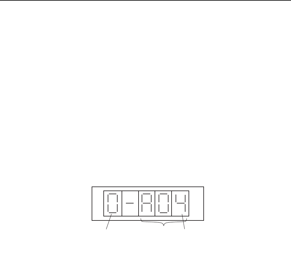
2 Press [DSPL/SET]- [DATA ENTER] to display the alarm code at the LED indi-
cator.
3 It is possible to scroll through the alarm sequences by pressing the Up or Down
arrow key.
Using the indicator panel on the servo amplifier
1 Press the [MODE/SET] button, and then press and hold the [DATA/SHIFT] but-
ton for at least one second to display previous alarm codes.
2 It is possible to scroll through the alarm sequences by pressing the Up or Down
arrow key. (The alarm sequence number (at the left side of the code) is displayed
in ascending order, starting with the most recent alarm code.)
Alarm sequence number
Alarm code
The alarm sequence number is displayed
in ascending order, starting with the most
recent alarm code
QP3M4022E

Troubleshooting >> Troubleshooting Table
MEC-CP842-1.0E 8-1
8. Troubleshooting
8.1 Troubleshooting Table
Point
This chapter describes troubleshooting measures for problems that may occur during
production.
Separate troubleshooting tables are provided for each type of problem. When a problem
occurs, begin by identifying the appropriate table for the problem in question, then refer to
the "Cause" column of that table to find the problem cause. After locating the cause, refer
to the "Remedy" and "Remarks" columns to the right of that item for details regarding
corrective actions. The "Ref. Page" column at the far right of the table indicates reference
material (manuals, etc.) chapter numbers where information is given regarding the
procedure in question.
The following alphabetic codes are used in the "Ref. Page" column to indicate reference
materials:
M: CP-842E/842ME Mechanical Reference (MEC-CP842-Preliminary)
S: CP-842E/842ME System Reference (SYS-CP842-Preliminary)
T: FujiCam Tutorial Manual (EKEN301*)
U: F4G User's Manual (ELEN013*)
FM: CP Feeders Mechanical Reference (MEC-CPFDR-*.*E)
FJ: CP Tape Feeder Jig Instruction Manual (INS-CPFJG-*.*E)
SG: Feeder Setup Guide (GDE-FEEDER-*.*E)
PG: WC Feeder Pickup Position Adjustment Guide (GDE-PKUPT-*.*E)