MEC-CP842-1.0E.pdf - 第167页
Adjustments >> Station Adjustments MEC-CP842-1.0E 7-31 Adjusting the Nozzle DOWN Limit Sensors The nozzle DOWN limit sensor that detects the down limit position of the nozzle UP/ DOWN rod is m ounted inside the cam…
Adjustments >> Station Adjustments
7-30 MEC-CP842-1.0E
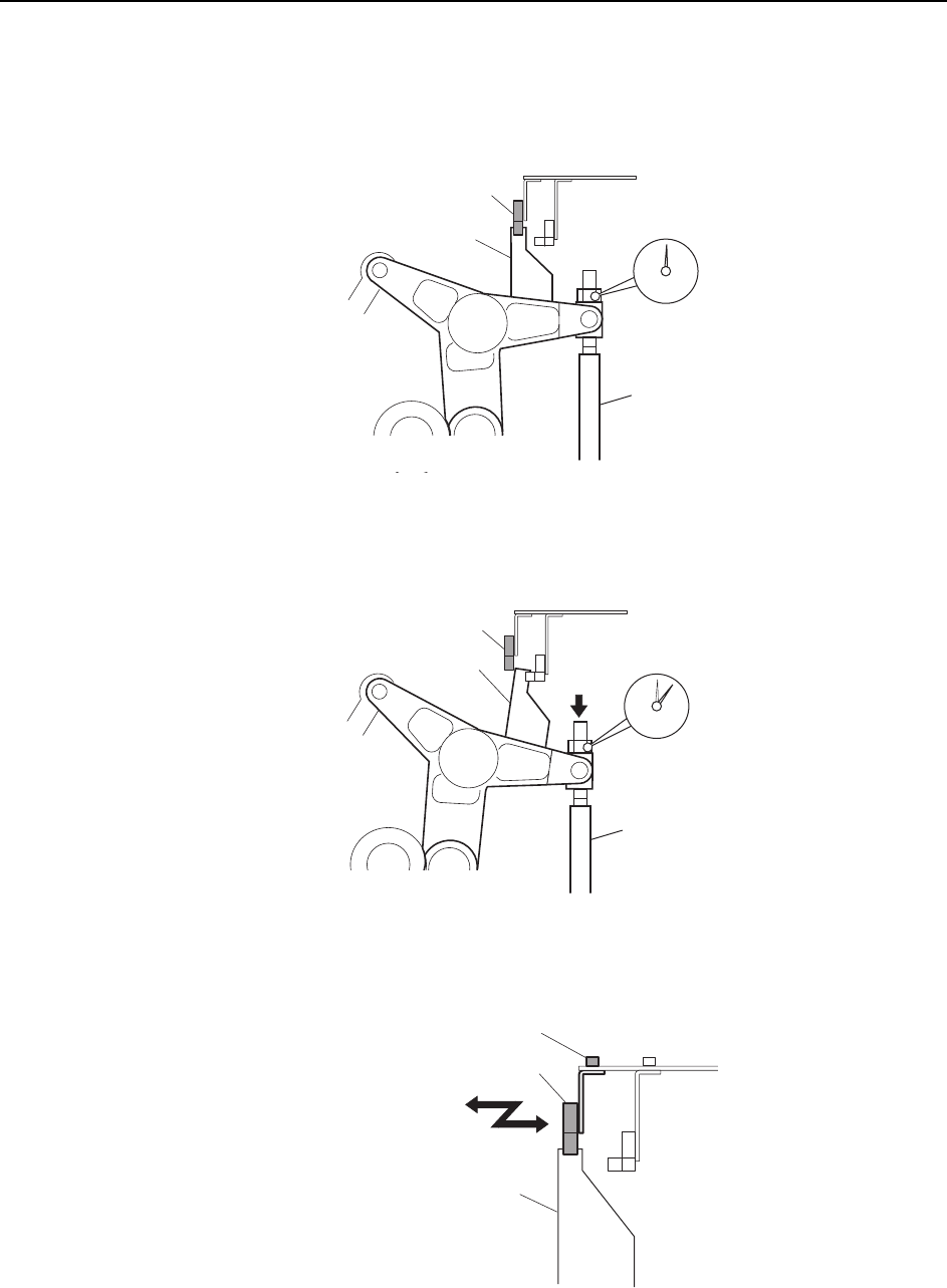
4 Place a dial gauge on the top end of the cam lever and zero the gauge. In this
condition, the cam axis will be at its 0° position, and the nozzle UP/DOWN rod
will be at its UP limit position. Verify that the nozzle UP limit sensor is ON
(X032 ST9 CYLINDER UPPER LIMIT is ON).
5 While observing the dial gauge, advance the cam to lower the nozzle UP/DOWN
rod. Adjust the sensor position so that the sensor switches OFF (X032 ST9
CYLINDER UPPER-LIMIT) when the rod is lowered 0.3 to 0.4 mm.
Adjust the sensor position by loosening the sensor lock screw and sliding the
sensor forward or backward.
C7SM4030
Nozzle up limit sensor (ON)
Dog
Nozzle UP/DOWN rod
Set the dial gauge
to "0"
C7SM4031
Nozzle up limit sensor (OFF)
Dog
Nozzle Up/Down rod
Rod lowered 0.3 to 0.4 mm
C7SM4032
Nozzle up limit sensor
Screw
Dog
Adjustments >> Station Adjustments
MEC-CP842-1.0E 7-31
Adjusting the Nozzle DOWN Limit Sensors
The nozzle DOWN limit sensor that detects the down limit position of the nozzle UP/
DOWN rod is mounted inside the cam box. Adjust the position of this sensor so that it
switches ON when the nozzle is at its DOWN limit position.
Note: If adjusting the DOWN limit sensor after the UP limit sensor, remove the dial gauge from the
machine to avoid interference between the dial gauge and the cam lever.
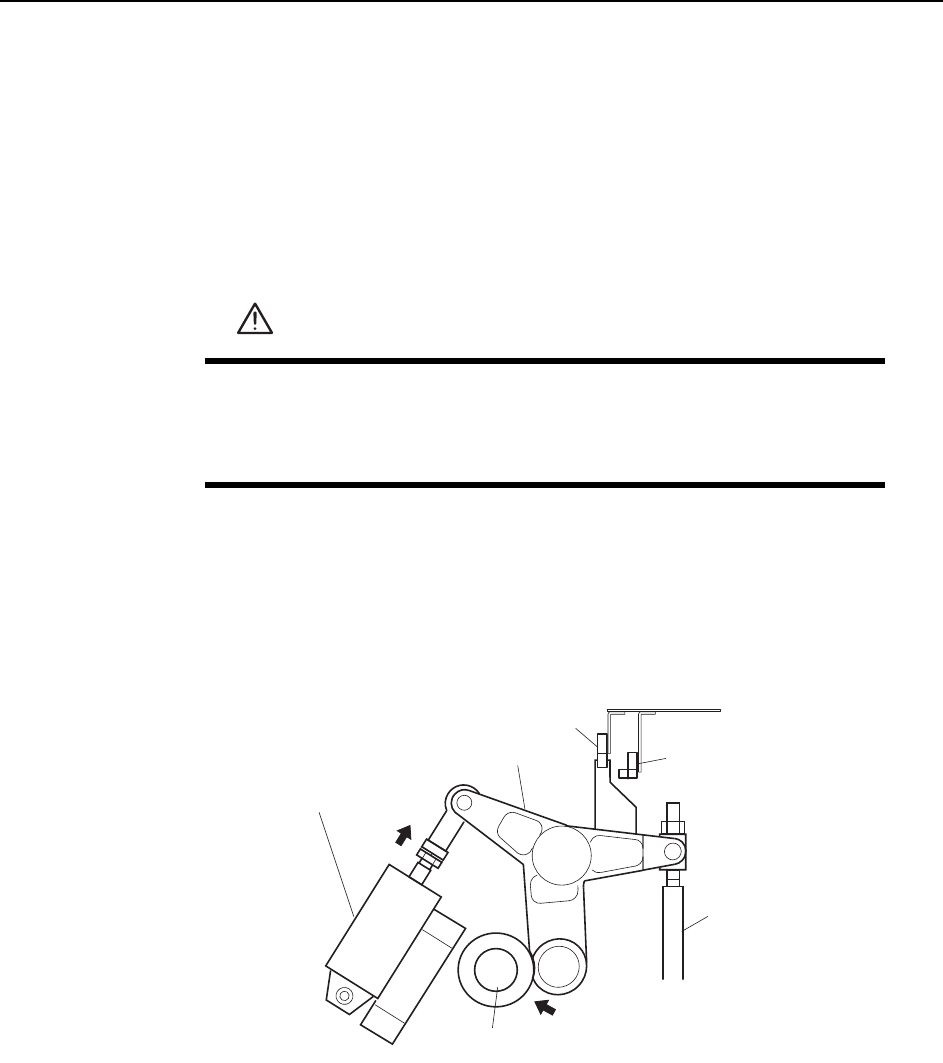
1 Press the EMERGENCY STOP button to take 200V down to 100V.
2 Set the cam axis at 0°.
3 Activate the ST9 placing solenoid air cylinder (located in the cam box):
Execute the following I/O commands: [Maintenance] - [I/O Check] - [Standard I/
O] - [Y035 ST9 PLACE SOL ENGAGED] - [Output Signal ON]
The cam lever will then follow the cam.
WARNING
• Press EMERGENCY STOP before performing this procedure.
• Exercise extreme caution when working on the machine if the cam
is not at its origin (0 deg.). Spring recoil can rotate the cam inde-
pendently.
ST9 Place solenoid
air cylinder
Cam lever
Nozzle UP/DOWN rod
Cam axis
Cam lever follows
the cam.
C7SM4029a
Nozzle up limit sensor
Nozzle down limit sensor
Adjustments >> Station Adjustments
7-32 MEC-CP842-1.0E
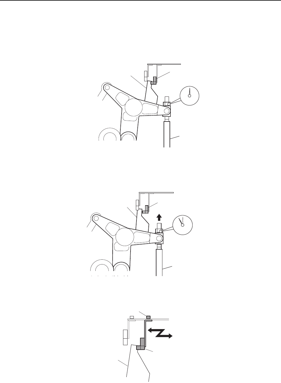
4 Use the cam handle to rotate the cam to 190°.
5 Place a dial gauge on the top end of the cam lever and zero the gauge. In this
condition, the nozzle UP/DOWN rod will be at its DOWN limit position. Verify
that the nozzle DOWN limit sensor is ON (X033 ST9 CYLINDER LOWER-
LIMIT) at the I/O screen.
6 While observing the dial gauge, advance the cam to raise the nozzle UP/DOWN
rod. Adjust the sensor position so that the sensor switches OFF (X033 ST9
CYLINDER LOWER-LIMIT) when the rod has been raised 0.3 to 0.4 mm.
Adjust the sensor position by loosening the sensor lock screw and sliding the
sensor forward or backward.
C7SM4033
Set the dial gauge to "0".
Nozzle down limit sensor (ON)
Dog
Nozzle UP/DOWN rod
C7SM4034
Nozzle down limit sensor (OFF)
Nozzle UP/DOWN rod
Rod raised 0.3 to 0.4 mm.
Dog
C7SM4035
Nozzle down limit senso
r
Screw
Dog