MEC-CP842-1.0E.pdf - 第56页
Basic Operati on >> Sett ing the Feeders 4-6 MEC-CP842-1.0E 13 and 15 i nch parts reels should be p ositioned u sing the three rubber stoppe rs. When setting, ensure that the feeder base and reel itse lf are positi…
Basic Operation >> Setting the Feeders
MEC-CP842-1.0E 4-5
4.3 Setting the Feeders
Point
Feeders must be set on the pallets in the correct manner in order for the nozzles to
pick up parts. Refer to the CP Feeders Mechanical Reference (MEC-CPFDR-x.xE) for
additional details.
Procedure
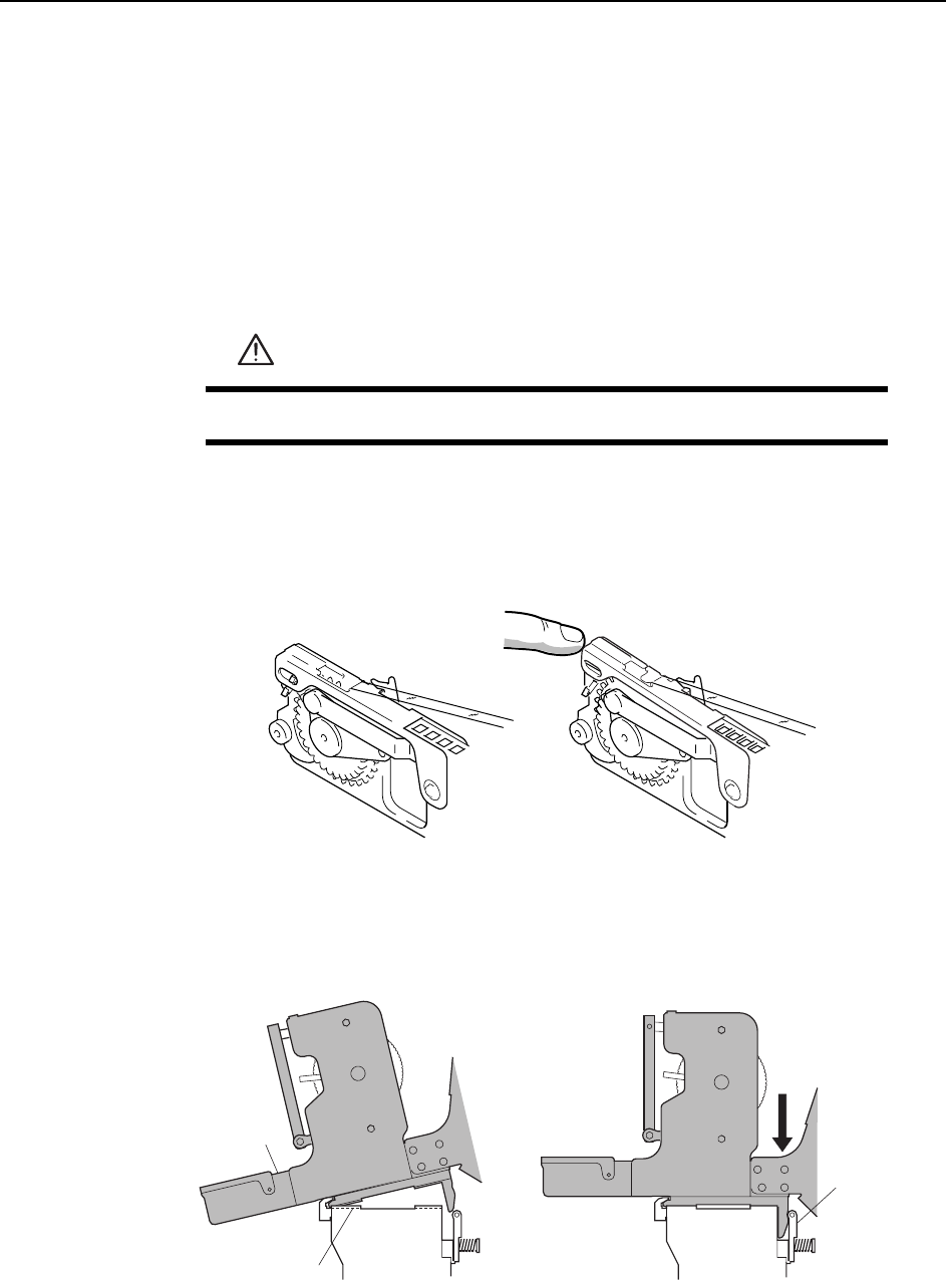
1 Verify that the tape guide is not deformed.
2 Load the part tapes in the appropriate feeders. If a part tape is loaded in the
wrong feeder, then the tape guide may not close properly.
3 Insert the catch on the base of the feeder into the channel beneath the guide.
Push the feeder forward and then press the back of the feeder to clamp it firmly
in position.
WARNING
Press EMERGENCY STOP before performing this procedure.
C746M200
6
Correct Incorrect
C746M2007
Clampe
r
Guide channel
Feeder
Basic Operation >> Setting the Feeders
4-6 MEC-CP842-1.0E
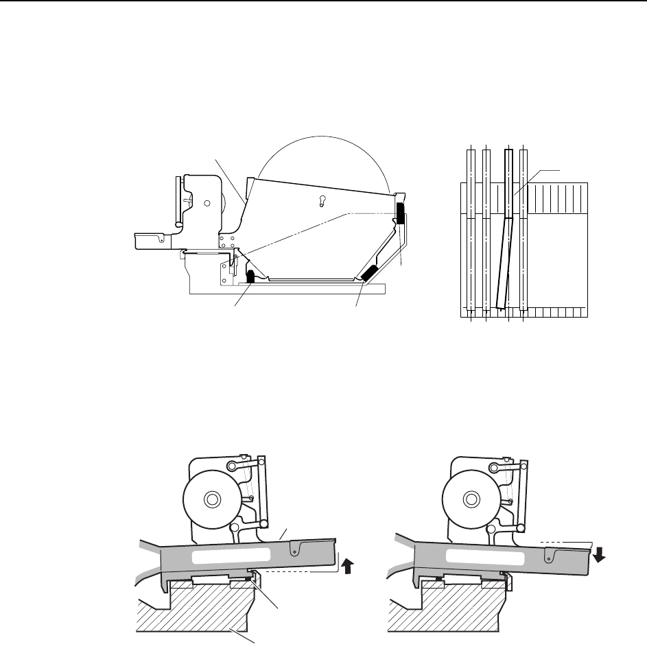
13 and 15 inch parts reels should be positioned using the three rubber stoppers.
When setting, ensure that the feeder base and reel itself are positioned in the
same slot. Correct parts supply will not be possible if feeders are set incorrectly,
as shown in the figure below.
4 When setting a feeder on a device table, check for waste tape, etc. between the
feeder and the device table. Remove any foreign matter from the device table
grooves and the bottom of the feeder.
C746M2008
Reel holder
Rubber brace Rubber brace
Rubber brace
View of device table from above
A
C746M2009
Waste tape
Device table
Feeder
Basic Operation >> Removal and Installation of Rotary Holders
MEC-CP842-1.0E 4-7
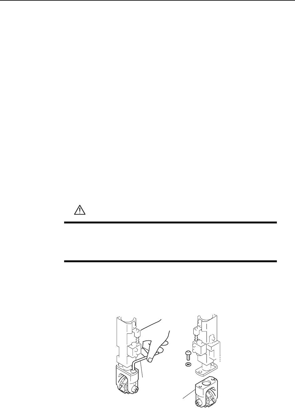
4.4 Removal and Installation of Rotary Holders
Point
Remove rotary holders from the placing heads as necessary when performing mainte-
nance such as cleaning and lubrication.
Note: The rotary holder is exclusive to the CP-842E/842ME. Do not attempt to use on any other
machines.
Do not use rotary holders from other machines on the CP-842E/842ME. In particular, rotary
holders from CP-7-series machines will interfere with other mechanisms around the turret
and damage the machine.
Rotary holders can be identified as follows.
CP-842E/842ME: No coloring
CP-6, CP-7 machines: Colored body (anodized)
Procedure
Complete the following 3 items before removing a rotary holder.
1 Move the rotary holder to station 9.
2 Move the XY-table towards the front of the machine to improve access.
3 Turn the machine power OFF.
Removal
1 Loosen the rotary holder mounting bolts with an Allen wrench.
2 Pull the rotary holder down to remove it from the shaft.
WARNING
• Turn the main power off before performing this procedure.
• Exercise extreme caution when working on the machine if the cam
is not at its origin (0 deg.). Recoil of the cam axis can endanger
the operator.
Allen wrench
Rotary holder
C746M2011