MEC-CP842-1.0E.pdf - 第151页
Adjustments >> Station Adjustments MEC-CP842-1.0E 7-15 9 Ensure that the clearance of the pin from the bracket is with in the range of 0.5 to 1.0 mm after the pin has been raised by the lever . 0.5~1.0 mm Pin brack…
Adjustments >> Station Adjustments
7-14 MEC-CP842-1.0E
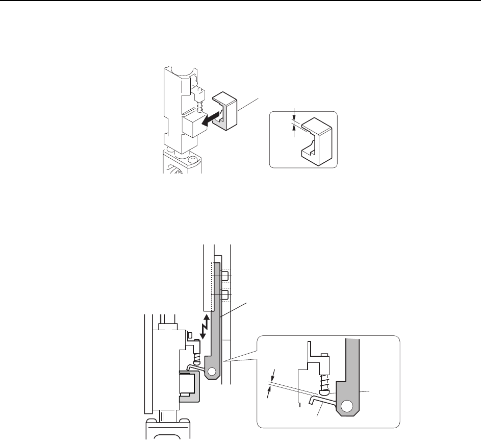
4 Slide the jig (Z9827DGPJ029*) over the mechanical valve from the side, as
shown in the diagram.
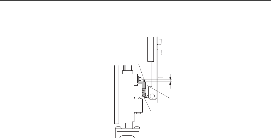
5 Adjust the height of the bracket so that the distance between the lever and the
pin is 0.6 mm.
6 Remove jig (Z9827DGPJ029*).
7 Return the cam angle to 0°. Switch on the 1st nozzle UP/DOWN solenoid valve
in order to work the cam lever.
Check the servo counter to verify that the Proper data (PICK UP POS. NZ) is at
the pick-up height (approx. 4000 pulse position).
8 Use the cam handle to rotate the cam to 170°.
C84PHD001E
,KI
( Z9827DGPJ029*)
3.2 mm
.GXGTDTCEMGV
C7SM4020Eb
0.6 mm
.GXGT
Pin
Adjustments >> Station Adjustments
MEC-CP842-1.0E 7-15
9 Ensure that the clearance of the pin from the bracket is within the range of 0.5
to 1.0 mm after the pin has been raised by the lever.
0.5~1.0 mm
Pin bracket
Pin
Lever
C7SM4021a
Adjustments >> Station Adjustments
7-16 MEC-CP842-1.0E
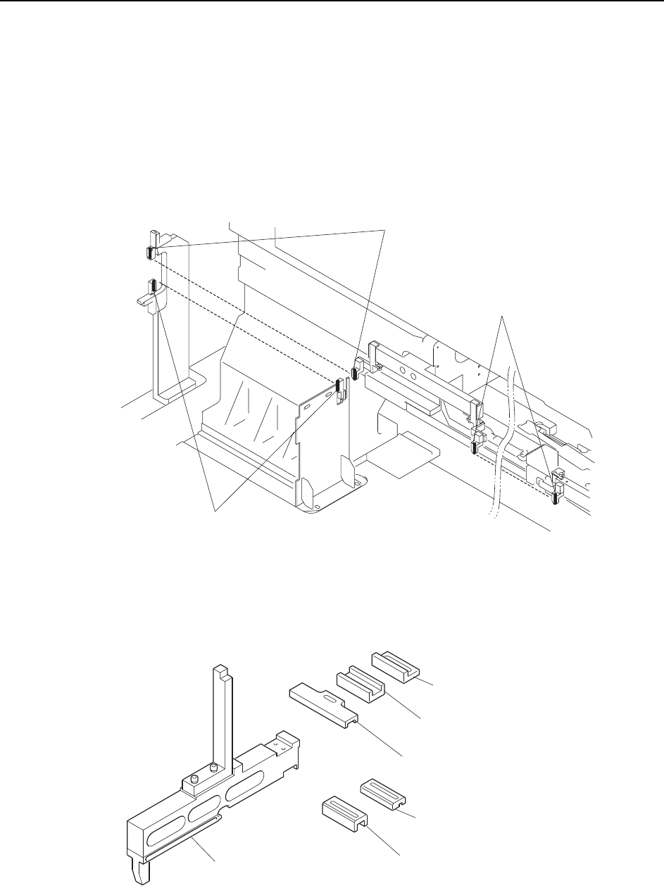
7.1.5 Feeder Height Error Detection (ST1)
Point
To detect the positions of the feeders, two sets of sensors are used at each of the retract
areas (D1, D2). Another pair of sensors is located at the pickup position, so there are
five sets in total.
A dedicated jig is used to position these sensors. The sensitivity of the sensors must
also be adjusted.
Note: This diagram shows the CP-842ME D1 arrangement, but the D2 arrangement is the same.
The jig used to adjust the sensor positions is shown below.
Feeder check sensor
(D1 retract area upper direction check)
Feeder check sensor
(D1 retract area lower direction check)
Feeder check sensor
(Pickup area upper direction check)
C7SM4022a
Positioning jig body
(ADCPJ8020)
Block
(DCPJ0040)
Block
(DCPJ0050) < For CP-842ME >
Block
(DCPJ0060)
Block
(DCPJ0070)
Block
(DGPJ5070) < For CP-842E >
C7SM4049b