MEC-CP842-1.0E.pdf - 第173页
Adjustments >> Station Adjustments MEC-CP842-1.0E 7-37 7.1.1 1 Reverse-thet a Mechanism (ST10) Point This mechanism reverses the nozzle rotation to the plac ement angle, which occurred at stations 2 and 8. Clutch M…
Adjustments >> Station Adjustments
7-36 MEC-CP842-1.0E
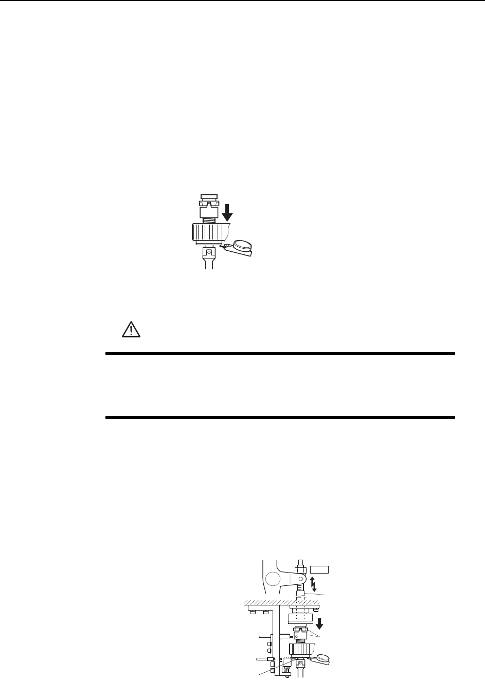
7 Loosen the mounting bolts shown in the figure below, then adjust the lever
height until there is a 0.2 mm gap (use a feeler gauge) between the bottom of the
mechanical valve and the lever.
Note: Do not touch the speed regulator.
The air-blow pressure is set to 15.0 ± 0.5 kPa (ST13: 7.0 ± 0.5 kPa). The user should not
change the setting unless a manometer is available for adjustment.
8 With the jig still on the shaft, move the shaft to ST10, 180°.
9 Remove the jig and return the mechanical valve and O-rings to the shaft. Lift
the mechanical valve against the top ridge and push it to the right against the
manifold (black plastic).
10 Tighten the mounting bolts with a torque of 0.8 N.m (8Kgf.cm).
Lever
/QWPVKPIDQNVU
%GPVGTKPILKI
5RGGFEQPVTQNNGT
0.2 mm
C7SM4037Eb
0.2 mm
C84PHD004E
/CPKHQNF
Adjustments >> Station Adjustments
MEC-CP842-1.0E 7-37
7.1.11 Reverse-theta Mechanism (ST10)
Point
This mechanism reverses the nozzle rotation to the placement angle, which occurred
at stations 2 and 8.
Clutch Meshing Check
Perform this check on the LOW nozzle.
Note: The LOW nozzle refers to the nozzle shaft with the shortest vertical stroke when pushed
down by the clutch. Use the LOW nozzle for checking the stroke at stations 2, 8 and 10.
1 Press the EMERGENCY STOP button to take the 200V down to 100V.
2 Set the cam angle to 0° and turn on the ST10 solenoid valve. The nozzle shaft
should descend when the cam is advanced.
3 Zero the dial gauge on the bottom of the nozzle shaft brake when there is no con-
tact between the clutches.
4 Use the cam handle to rotate the cam to 200°.
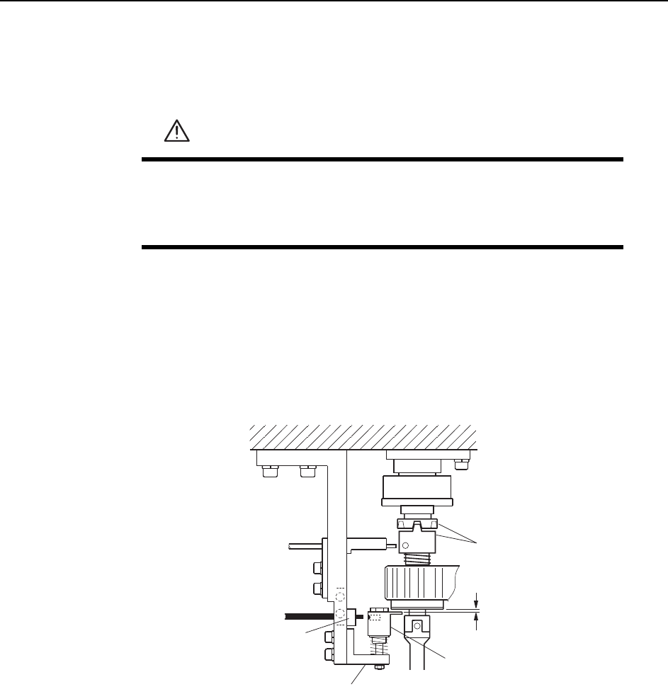
5 Ensure that the clutches mesh properly and that the nozzle shaft deflects the
dial gauge 0.30 ~ 0.35 mm, as illustrated below.
WARNING
• Press EMERGENCY STOP before performing this procedure.
• Exercise extreme caution when working on the machine if the cam
is not at its origin (0 deg.). Spring recoil can rotate the cam inde-
pendently.
Measure the vertical stroke
at all nozzles to determine the
lowest value.
C7SM4058
Clutch
ST10
Rod
0.30~0.35 mm
C7SM4038a
Measure the
vertical stroke
Nozzle shaft brake
Adjustments >> Station Adjustments
7-38 MEC-CP842-1.0E
Clutch Meshing Check Sensor Position Adjustment
1 Press the EMERGENCY STOP button to take the 200V down to 100V.
2 Use the cam handle to rotate the cam to 200°.
3 Use the inching keys to align the RQ-axis with the RQ-data position.
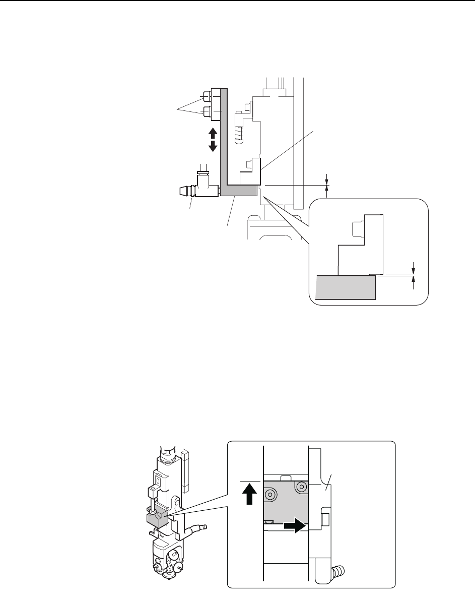
4 Make sure the clutches engage properly. Adjust the height of Bracket A so that
Gap C in the figure is 0.2 mm.
5 At this position, adjust the position of Bracket B so that the sensor beam enters
the hole on the dog.
WARNING
• Press EMERGENCY STOP before performing this procedure.
• Exercise extreme caution when working on the machine if the cam
is not at its origin (0 deg.). Spring recoil can rotate the cam inde-
pendently.
Dog
Clutch
Bracket A
Bracket B
C7SM4039a
0.2 mm
C