MEC-CP842-1.0E.pdf - 第191页
Troubleshooting >> Troubles hooting Table MEC-CP842-1.0E 8-1 8. T roubleshooting 8.1 T roubleshooting T able Point This chapter describes tro ubleshooting meas ures for problems that may occur duri ng production. S…
Adjustments >> Servo Amplifier Adjustments
7-54 MEC-CP842-1.0E
7.2.2 Resetting servo errors
Servo errors that cannot be reset using commands at the machine can be reset by con-
necting the digital operator to the applicable servo amplifier and pressing the [Alarm
Reset] button.
Servo alarm codes
When a servo amplifier error occurs, you can view the alarm code by connecting the
digital operator to the applicable amplifier. For further details regarding alarm codes,
see 8.2.2 Alarm Codes and Troubleshooting Check List.
Servo alarm code history
It is possible to view previous alarm codes, either by using the digital operator or by
using the indicator panel on the servo amplifier.
Using the digital operator
1 Connect the Digital Operator cable to the applicable servo amplifier (CN-3 con-
nector).
2 Press [DSPL/SET]- [DATA ENTER] to display the alarm code at the LED indi-
cator.
3 It is possible to scroll through the alarm sequences by pressing the Up or Down
arrow key.
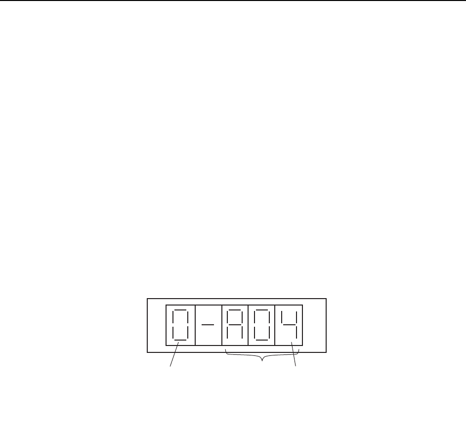
Using the indicator panel on the servo amplifier
1 Press the [MODE/SET] button, and then press and hold the [DATA/SHIFT] but-
ton for at least one second to display previous alarm codes.
2 It is possible to scroll through the alarm sequences by pressing the Up or Down
arrow key. (The alarm sequence number (at the left side of the code) is displayed
in ascending order, starting with the most recent alarm code.)
Alarm sequence number
Alarm code
The alarm sequence number is displayed
in ascending order, starting with the most
recent alarm code
QP3M4022E

Troubleshooting >> Troubleshooting Table
MEC-CP842-1.0E 8-1
8. Troubleshooting
8.1 Troubleshooting Table
Point
This chapter describes troubleshooting measures for problems that may occur during
production.
Separate troubleshooting tables are provided for each type of problem. When a problem
occurs, begin by identifying the appropriate table for the problem in question, then refer to
the "Cause" column of that table to find the problem cause. After locating the cause, refer
to the "Remedy" and "Remarks" columns to the right of that item for details regarding
corrective actions. The "Ref. Page" column at the far right of the table indicates reference
material (manuals, etc.) chapter numbers where information is given regarding the
procedure in question.
The following alphabetic codes are used in the "Ref. Page" column to indicate reference
materials:
M: CP-842E/842ME Mechanical Reference (MEC-CP842-Preliminary)
S: CP-842E/842ME System Reference (SYS-CP842-Preliminary)
T: FujiCam Tutorial Manual (EKEN301*)
U: F4G User's Manual (ELEN013*)
FM: CP Feeders Mechanical Reference (MEC-CPFDR-*.*E)
FJ: CP Tape Feeder Jig Instruction Manual (INS-CPFJG-*.*E)
SG: Feeder Setup Guide (GDE-FEEDER-*.*E)
PG: WC Feeder Pickup Position Adjustment Guide (GDE-PKUPT-*.*E)
Troubleshooting >> Troubleshooting Table
8-2 MEC-CP842-1.0E
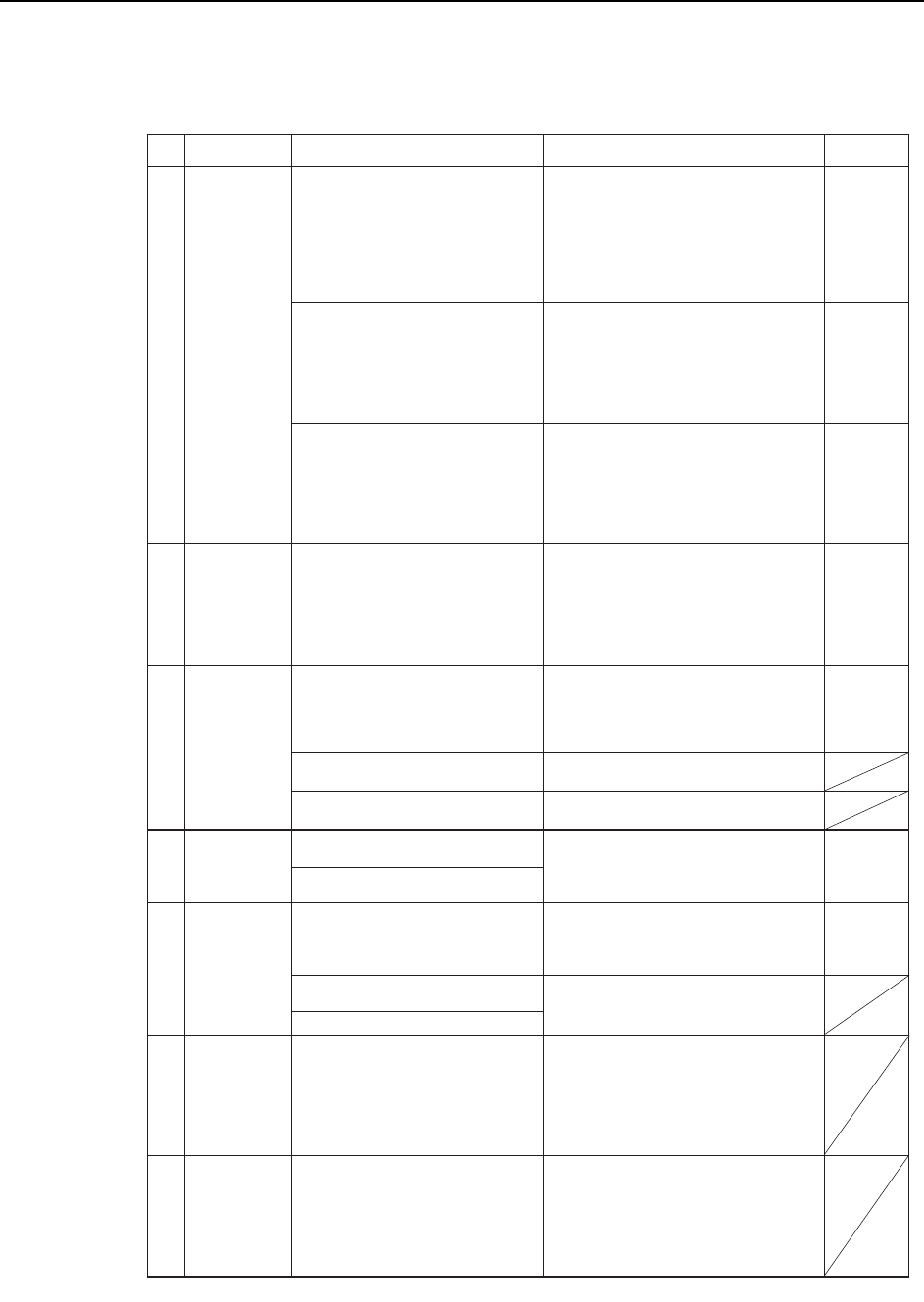
8.1.1 Poor Placing Accuracy
No.
T: Part 3,
Lesson 2
"2.1.3"
U: Part 2
Chapt 4
"Nozzle"
"Speed"
T: Part 3
Lesson 2
"2.1.3"
U: Part 2
Chapt 4
"Speed"
T: Part 3
Lesson 2
"2.1.1"
U: Part 2
Chapt 4
"Appearance"
M: Sect 6.1
M: Sect 4.1
M:Sect 7.1.4
1-1
1-2
1-3
1-4
M:Sect 9.1
1-5
1-6
1-7
Setting error
in Part data.
Specify the appropriate nozzle size and
cam speed settings using the Fuji SMT
Report as a reference.
If accuracy deviations or defects are
occurring for a specific part, decrease
the XY table speed setting in the Part
data where the problem is occurring.
Check for errors in the part height
information.
Check the backup pin heights, quantity,
and configuration, and verify that the
panel is flat.
Check for a problem with the Proper
data Z0 (0.3 mm push in).
Check for reference and adjustable
rail flatness problems.
Replace mechanical valves if the
spool motion is not smooth.
Adjust the vacuum switch lever
position and speed controller.
(1) Use the nozzle check command to
check for bent nozzles.
(2) Verify that the nozzle spring-back
motion is smooth.
(3) Verify that the nozzle is not clogged.
If a problem is found with any of the
above, replace the nozzle.
Defective nozzle
Improper
placement
height
Vacuum switch
problem
Cause Remedy Remarks Ref. Page
Unsuitable nozzle size, part weight, and cam
speed, etc., settings can result in insufficient
part holding power, causing nozzle and part
slippage. Refer to the Fuji SMT report for
recommended cam speeds and nozzles.
An unsuitable XY table speed can apply a
force which exceeds the holding capacity of
the part's solder, resulting in position
deviations.
Solder adhesion decreases when it dries.
Therefore, the sooner placement occurs after
printing, the better.
"Missing parts" conditions may occur if there
is an error in the part height information, or
in the table reference height Proper
data.
Fuji recommends measuring the part
height, and entering the measured value in
Part data.
A bent or stuck nozzle will make it impossible
to place parts properly.
A misalignment between the ST9 nozzle
down limit and the panel height can prevent
the part from being pressed onto the board
properly, and it may become impossible to
maintain accuracy.
Note: Machine adjustments require advanced
training and skills.
Note: Machine adjustments require advanced
training and skills.
A malfunctioning mechanical valve may
reduce placing accuracy.
Note: Machine adjustments require advanced
training and skills.
The solder printing condition or dryness can
cause part deviations during board
conveyance, or can affect the self-alignment
at reflow operations.
Solder adhesion weakens when the solder
dries. Therefore, the sooner placement
occurs after printing, the better.
Improper reflow conditions can cause self-
alignments and tombstoning.
Provide a profile in which the temperature is
increased evenly over the entire board. If the
solder's melting speed differs from point to
point, parts will be pulled toward the solder
that melts first.
Failure to level the machine base after the
machine has been moved, etc., can effect the
XY-table flatness, making the current Proper
data unsuitable.
Verify that the machine base is level
(if not, level it).
Measure the X0/Y0 and camera
resolution.
Calibrate with PAM parts.
Check the solder condition after printing.
Check the reflow temperature profile.
Problem after
machine status
change.
Printing
conditions
problems.
Reflow
conditions
problems.
C746M5TO1