MEC-CP842-1.0E.pdf - 第148页
Adjustments >> Station Adjustme nts 7-12 MEC-CP842-1.0E 7.1.4 Mechanical V a lve Switching (ST1) Point The nozzle vacuum goes from O FF to ON wi th the movement of the mechanical valve at station 1. V a cuum for pa…
Adjustments >> Station Adjustments
MEC-CP842-1.0E 7-11
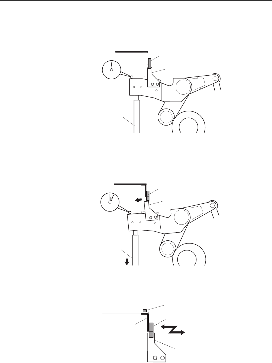
4 Place a dial gauge on the top end of the cam lever and set the gauge reading to
“0”. In this condition, the cam axis will be at 0°, and the nozzle UP/DOWN rod
will be at its UP limit position. Verify that the nozzle UP limit sensor is ON
(X030 ST1 CYLINDER UPPER-LIMIT is ON) at the I/O screen.
5 While observing the dial gauge, rotate the cam axis in the forward direction to
lower the nozzle UP/DOWN rod. Adjust the sensor’s mounting position so that
the sensor switches OFF (X030 ST1 CYLINDER UPPER-LIMIT switches OFF)
when the rod has been lowered 0.3 to 0.4 mm.
6 Adjust the sensor’s mounting position by loosening the sensor lock screw and
sliding the sensor in the front/back directions.
C7SM4016
Dog
Nozzle UP/DOWN
rod
Set the dial gauge
to "0"
Nozzle up limit sensor (ON)
Dog
Nozzle UP/DOWN
rod
Nozzle up limit sensor (OFF)
C7SM4017
C7SM4018a
Nozzle up limit sensor
Screw
Sensor bracket
Dog
Adjustments >> Station Adjustments
7-12 MEC-CP842-1.0E
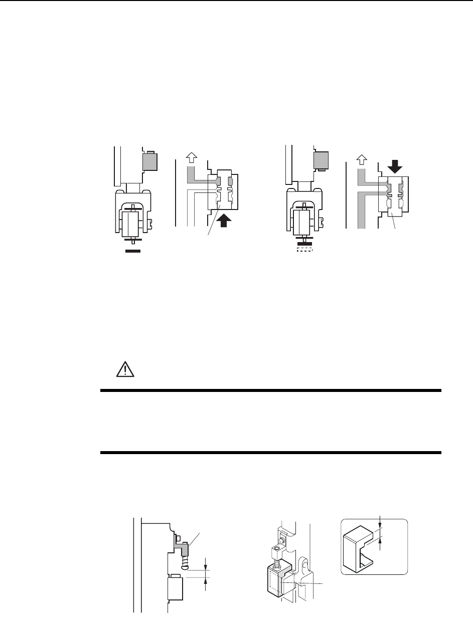
7.1.4 Mechanical Valve Switching (ST1)
Point
The nozzle vacuum goes from OFF to ON with the movement of the mechanical valve
at station 1. Vacuum for part pick-up reaches the nozzle when the valve is open.
Checking the Position of the Pin Bracket
1 Press the EMERGENCY STOP button to turn off the 200V power, leaving only
the 100V power on.
2 Ensure that distance A (as seen in the figure below) is 8.9 mm for all heads. Use
a special jig (Z9827DGPJ029*) to check this distance.
WARNING
• Press EMERGENCY STOP before performing this procedure.
• Exercise extreme caution when working on the machine if the cam
is not at its origin (0 deg.) Spring recoil can rotate the cam inde-
pendently.
Vaccum ONVaccum OFF
Vaccum
Vaccum
Spool
Spool
< Spool pushed up > < Spool pushed down >
C7SM4019a
8.9 mm
2KPDTCEMGV
,KI
( Z9827DGPJ029*)
8.9 mm
C7SM4054Eb
A
Adjustments >> Station Adjustments
MEC-CP842-1.0E 7-13
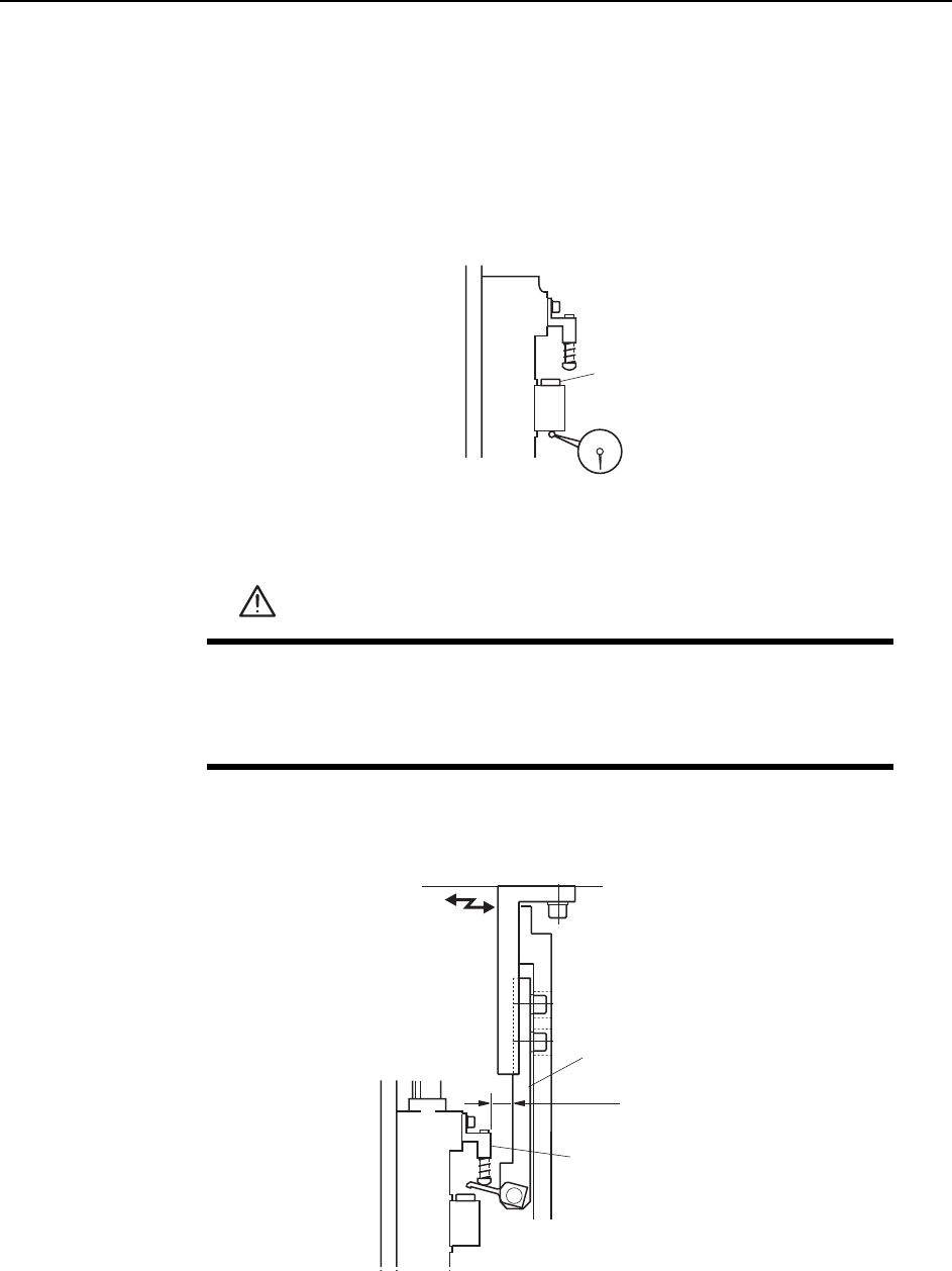
Valve Switching Lever Height Adjustment
This adjustment should be performed on the low valve shaft after completing
adjustments to the vertical movement of the nozzle. (Refer to 7.1.3 “Nozzle Verti-
cal Movement During Pickup” for details.) The low valve shaft can be identified
by measuring the lower surface of the mechanical valve spool on all shafts. Raise
the spools and measure with a dial gauge, as shown in the diagram below.
1 Press the EMERGENCY STOP button to take the 200V down to 100V.
2 Adjust the position of the lever bracket so that the distance from the pin bracket
is 12 mm.
3 With the Y030 ST1 PICKUP SOL DISENGAGED ON, use the cam handle to
rotate the cam to 170°.
WARNING
• Press EMERGENCY STOP before performing this procedure.
• Exercise extreme caution when working on the machine if the cam
is not at its origin (0 deg.). Spring recoil can rotate the cam inde-
pendently.
Spool
C7SM4055
Lever bracket
Pin bracket
C7SM4056
12 mm