00198168-02_Technical_Training_TX-Series_EN.pdf - 第106页
5 Placement Heads 5.2 C&P20 P/M2 Head 106 Technical Training SIPLACE TX-Series 10/2016 Pressure Control Valve (PRV) 1. Energy and data supply 2. Compressed air connection 3. Vacuum/air kiss for pickup/placement circu…
5 Placement Heads
5.2 C&P20 P/M2 Head
Technical Training SIPLACE TX-Series 10/2016 105
5.2.4.2 Vacuum System Main Parts
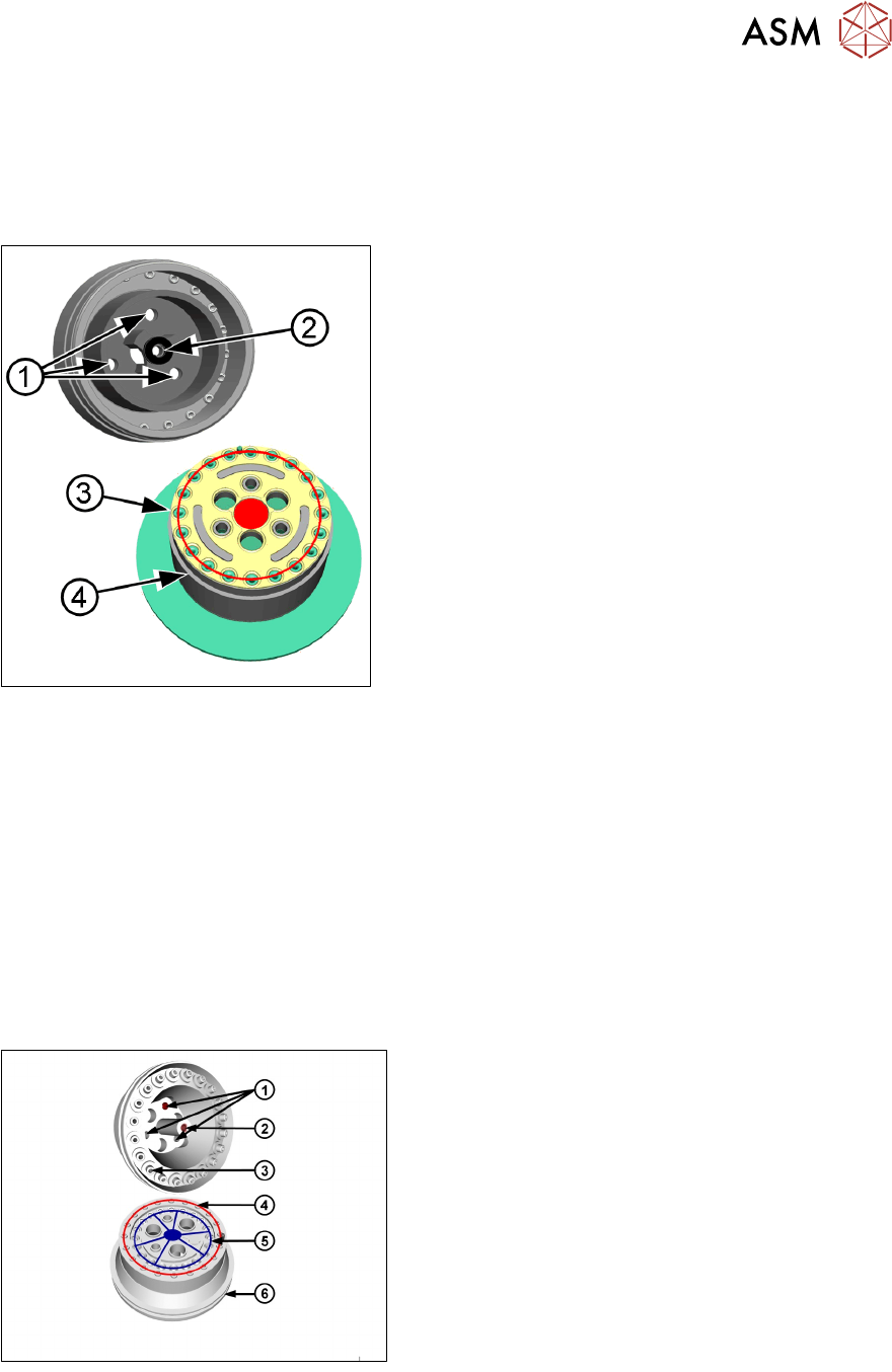
Holding Circuit (Vacuum Pump Operation)
In vacuum pump operation the holding circuit is directly supplied with vacuum by a reflecting ring.
With the first component vacuum will be applied to all segments creating vacuum leakages. To
keep them at a minimum a sealing is installed between reflecting ring and segments.
1. Mounting to the star frame
2. Mounting for the end cover
3. Vacuum to the segments
4. O-ring between vacuum unit and reflection ring
Vacuum pump operation with reflecting ring (Standard)
●
Standard is vacuum pump operation. The compressed air operation mode is an option.
●
The reflecting ring makes sure to seal the head against vacuum loss.
●
The vacuum is centralized distributed to the segments through the reflecting ring.
●
If a segment is in the pickup/placement circle, the holding circle vacuum is increased (during
pickup) or eliminated via air kiss (during placement) by the digital PRV.
Holding Circuit (Compressed Air Operation)
Pressurized air is supplied through the hollow star motor shaft to the holding circuit.
The holding circuit contains 20 small venturi nozzles. Each venturi nozzle supplies vacuum to the
corresponding segment. If a segment in the pick up-/placement-position, the vacuum of the holding
circuit increased (during pick up) or eliminated via air kiss (during placement) from the digital PRV.
Vacuum unit / Holding circle details
●
Mounting (1) to star frame
●
Mounting (2) for silencer
●
Venturi nozzle discharged air (3) to the silencer
●
Venturi nozzle vacuum outlet (4 red) to the
segments
●
Compressed air inlet (5 blue) to venturi nozzle.
The venturi nozzle entrances have seals
●
O-ring (6) between vacuum unit and silencer
5 Placement Heads
5.2 C&P20 P/M2 Head
106 Technical Training SIPLACE TX-Series 10/2016
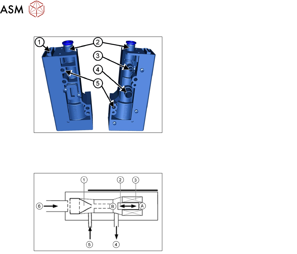
Pressure Control Valve (PRV)
1. Energy and data supply
2. Compressed air connection
3. Vacuum/air kiss for pickup/placement
circuit
4. Discharged air for cooling the X linear
motor
5. Mounting for pressure control valve
●
The PRV supplies the pickup/placement circuit with vacuum during the pickup process and
switches over to air kiss during placement.
●
The valve can be replaced during service work.
●
Sensitivity against dirt and dust is reduced (protection diaphragm).
A - Piston in "open" position
B - Piston in "closed" position
1. Venturi nozzle
2. Plunger (iron core)/ piston
3. Plunger drive (inductor)/ driver circuit
4. Discharged air
5. Vacuum/air kiss for pickup/placement
circuit
6. Compressed air inlet
●
During pickup, the piston is always in the "open" position; vacuum is produced and applied to
nozzle for pickup.
●
During placement, the piston is in the "close" position, air kiss is produced and applied to
nozzle for placement.
●
In the placement cycle the time to switch between maximum vacuum (-850 mbar) to maximum
air kiss (+400 mbar) is < 12ms.
5 Placement Heads
5.2 C&P20 P/M2 Head
Technical Training SIPLACE TX-Series 10/2016 107
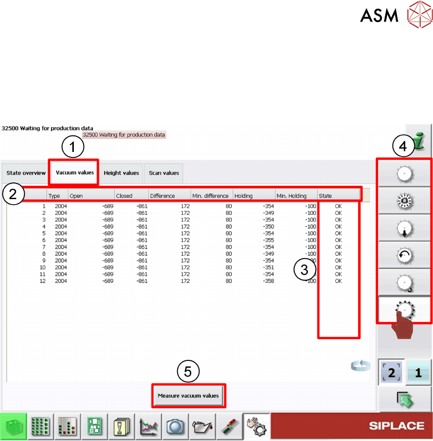
5.2.4.3 GUI – How to Perform a Vacuum Check
In the case of vacuum errors the vacuum system can be tested using the station software.
For the pickup/placement circuit the differences between open and closed values are evaluated,
for the holding circuit the absolute value is measured.
1. Check Vacuum values tab
2. Nozzle vacuum detailed results
3. Nozzle vacuum check status
4. Head function menus
5. Click Measure vacuum values to start new check.
When vacuum results are bad the segment/segments affected are highlighted.
Example: Error occur on segment 3