00198168-02_Technical_Training_TX-Series_EN.pdf - 第111页
5 Placement Heads 5.2 C&P20 P/M2 Head Technical Training SIPLACE TX-Series 10/2016 111 5.2.5.3 DP drive Power supply 1. Power cube for generating 30VDC/5.2A from 40VDC 2. Base adapter 3. Flat ribbon cable 4. Intermed…
5 Placement Heads
5.2 C&P20 P/M2 Head
110 Technical Training SIPLACE TX-Series 10/2016
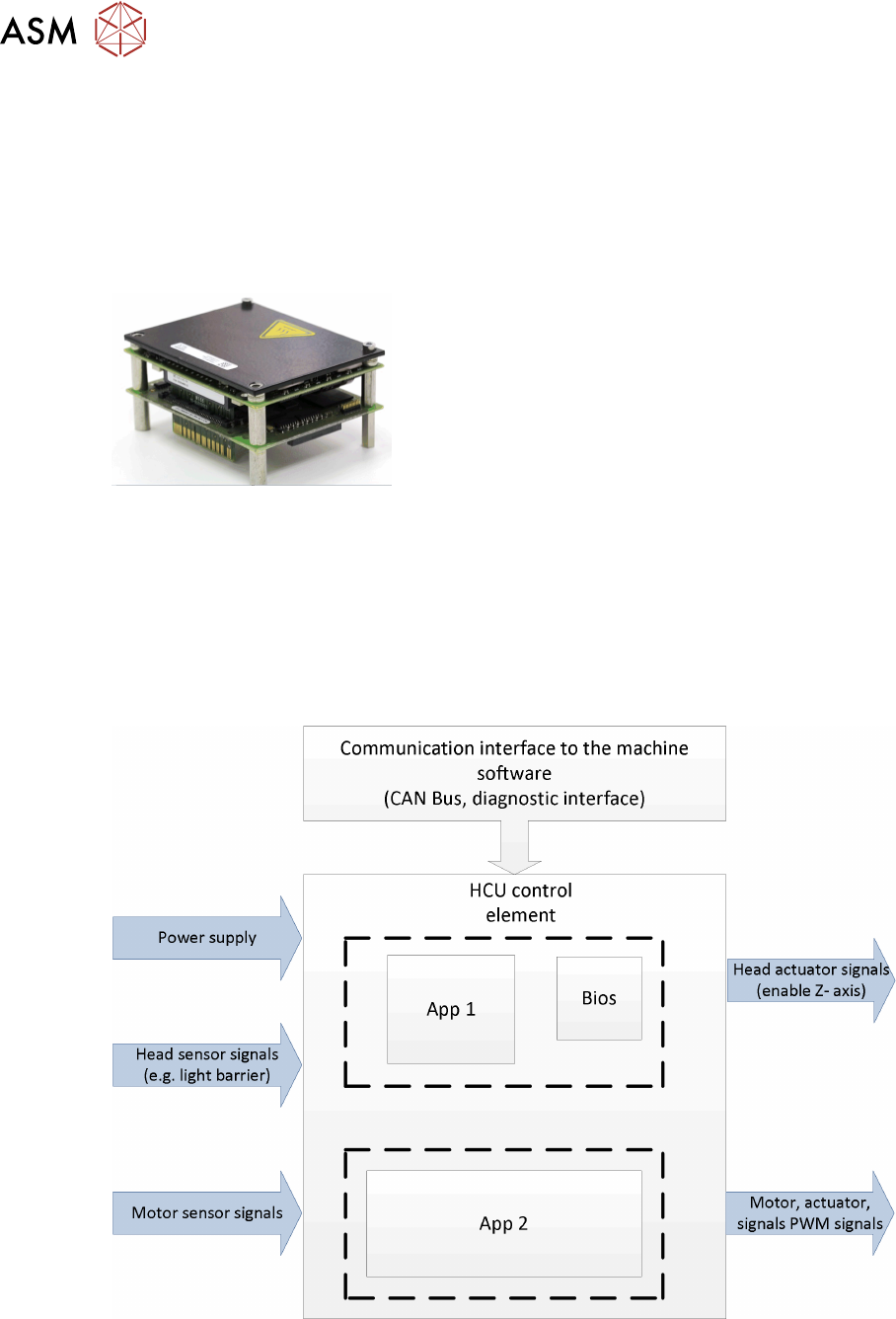
5.2.5.2 MHCU General
The task of the MHCU is the position control of the head axis (C&P20, CPP und Twin Head).
Further the MHCU integrates the functions of the PRV, the component sensor and the
communication interface for the DP Axis.
The unit consists of a control module (CM) and a power module (PM) comparable to the axis card
as control module and the servo card as power module.
MHCU Function Power Supply
●
The power supply delivers 42V for the electronic and Z Axis.
●
The power cube on the head interface (C700) supplies the MHCU with 25V.
●
All required internal voltages (+24V, +15V, -15V, +5V, +3.3V, +1.5V) are generated by the
head interface at the gantry.
●
In addition, the operating voltages for the axes (150 V for star / 42V for Z-) are supplied by
MGCU.
MHCU Function
The head control unit is responsible for central control, adjustment of the axis and for communica-
tion with the computer system via CAN bus.
Tasks of the software application:
●
BIOS is responsible for the booting of the MHCU (Tri-core)
●
Application 1: communication with machine software
●
Application 2: motor control
5 Placement Heads
5.2 C&P20 P/M2 Head
Technical Training SIPLACE TX-Series 10/2016 111
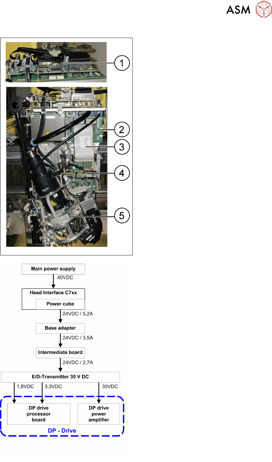
5.2.5.3 DP drive Power supply
1. Power cube for generating 30VDC/5.2A
from 40VDC
2. Base adapter
3. Flat ribbon cable
4. Intermediate board
5. E/D – Transmitter
●
42VDC are supplied from the main power
supply
●
The 30V DC are generate on the E/D
Transmitter
●
On the E/D-Transmitter the following
voltages are generated from the 30VDC:
– 1,8VDC for the processors
– 3,3VDC for the processors
– 30VDC routed directly to the DP drives
5 Placement Heads
5.2 C&P20 P/M2 Head
112 Technical Training SIPLACE TX-Series 10/2016
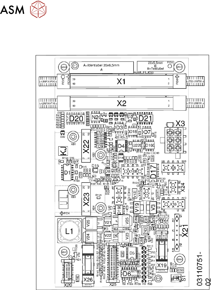
5.2.6 Board description
5.2.6.1 Intermediate Distributor Board Functions
●
The connection leads for all C&P20 head electrical sensors and actuators are directly plugged
into the intermediate board
●
LEDs indicate the head operating voltages and the sensor states
●
Test connectors for track signals, test pins for analog signals
●
Controlled power supply for incremental encoder of Z and star drives
●
Interface for component sensor, vacuum unit, hold circuit vacuum sensor and EEPROM
●
Signal conditioning of vacuum sensor in hold circuit, of component sensor and Z-down sensor
●
Signal preprocessing of head CAN bus
●
Trigger circuit for retract unit
●
DIP-Switch for diagnoses purposes