00198168-02_Technical_Training_TX-Series_EN.pdf - 第68页
5 Placement Heads 5.1 CPP Head 68 Technical Training SIPLACE TX-Series 10/2016 5.1.4.2 GUI – How to perform a vacuum check In the case of vacuum errors the vacuum system can be tested using the station software. For the …
5 Placement Heads
5.1 CPP Head
Technical Training SIPLACE TX-Series 10/2016 67
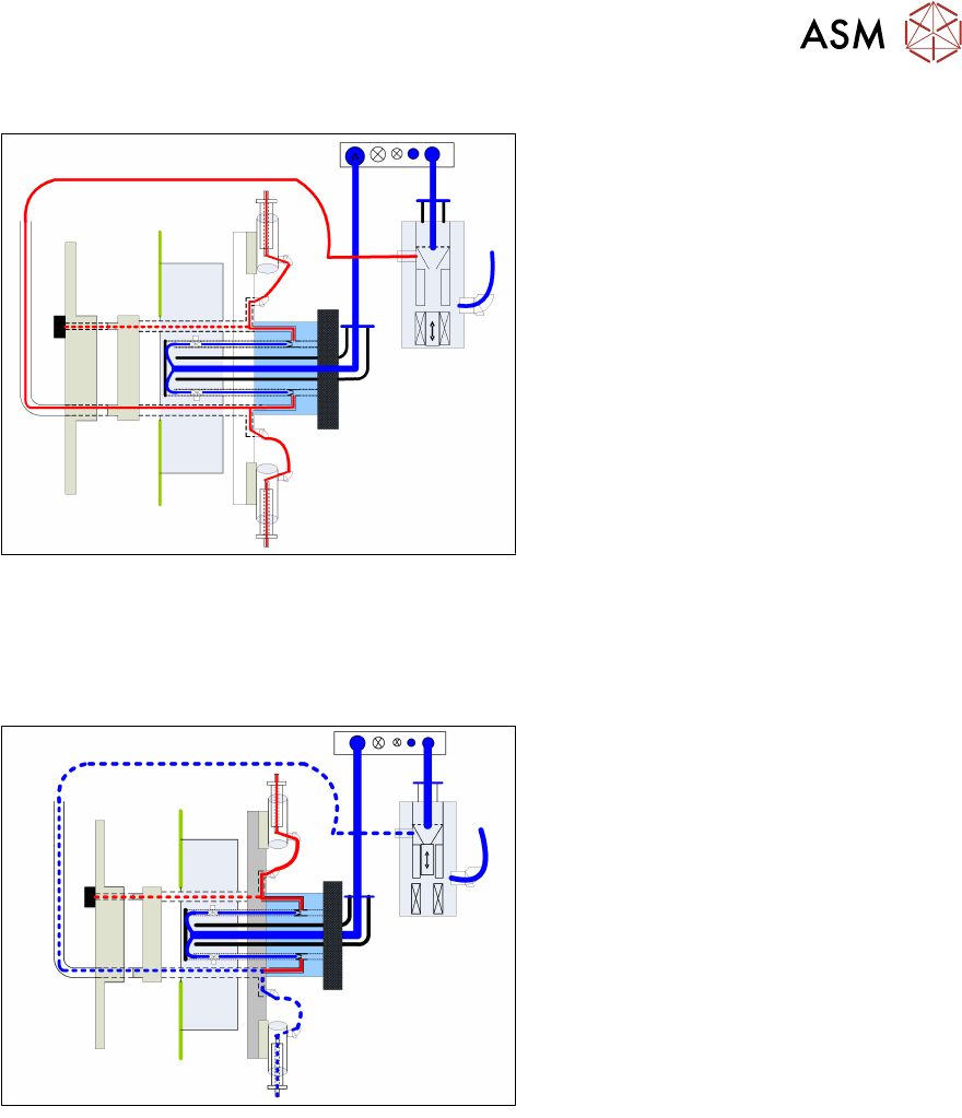
Pickup and Placement Circuit
●
Before the star rotates into the pickup position, the relevant valve is switched on via the valve
terminal.
●
Vacuum from the holding circuit is now present at the nozzle.
●
Once the star has reached the pickup position, the holding circuit vacuum is strengthened via
the PRV and the component can be picked up.
●
After the component has been picked up, the component is held on the nozzle with the
holding circuit.
●
Once in the placement position and the Z down sensor is enabled, the PRV will switch over to
air blast. This eliminates the holding circuit vacuum and an air blast of approx. 200mbar is
present at the nozzle.
5 Placement Heads
5.1 CPP Head
68 Technical Training SIPLACE TX-Series 10/2016
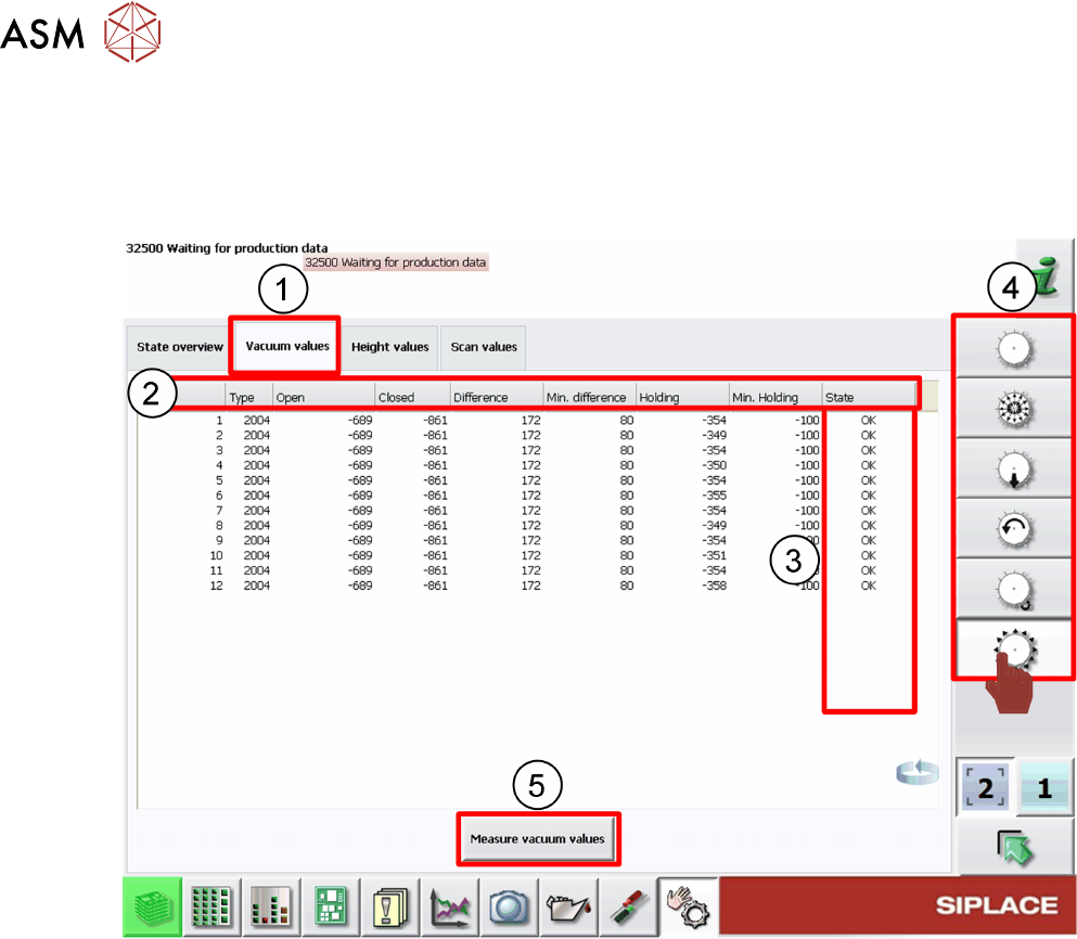
5.1.4.2 GUI – How to perform a vacuum check
In the case of vacuum errors the vacuum system can be tested using the station software.
For the pickup/placement circuit the differences between open and closed values are evaluated,
For the holding circuit the absolute value is measured.
1. Check Vacuum values tab
2. Nozzle vacuum detailed results
3. Nozzle vacuum check status
4. Head function menus
5. Click Measure vacuum values to start new check.
When vacuum results are bad the segment/segments affected are highlighted.
Example: Error occurs on segment 3.
5 Placement Heads
5.1 CPP Head
Technical Training SIPLACE TX-Series 10/2016 69
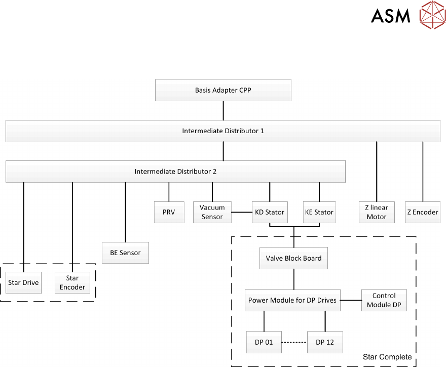
5.1.5 Overview Power Control and Communication