00198168-02_Technical_Training_TX-Series_EN.pdf - 第37页
4 Gantry System 4.1 Overview Technical Training SIPLACE TX-Series 10/2016 37 4 Gantry System 4.1 Overview The gantries of the SIPLACE TX machines consist of one X and one Y Axis. Both axes are driven by a linear motor wh…

3 Setting Up the Machine
Room for Your Sketches and Notes
36 Technical Training SIPLACE TX-Series 10/2016
4 Gantry System
4.1 Overview
Technical Training SIPLACE TX-Series 10/2016 37
4 Gantry System
4.1 Overview
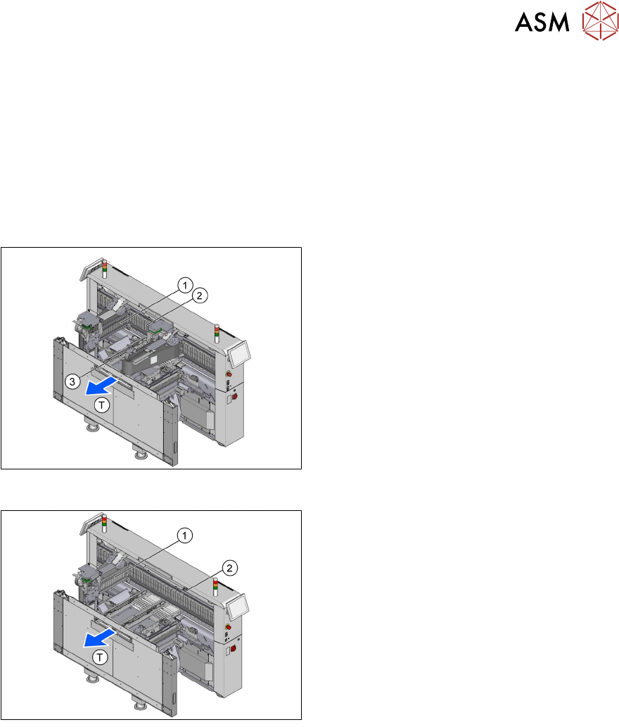
The gantries of the SIPLACE TX machines consist of one X and one Y Axis. Both axes are driven
by a linear motor which is equipped with an integrated temperature sensor. These temperature
sensors only monitor the motor coils. The placement heads are mounted on the head plates of the
respective XAxis.
TX2i/TX2
T - Transport direction
1. X Axis, Gantry 1
2. Y Axis, Gantry 1 and Gantry 2
3. X Axis, Gantry 2
TX1
T - Transport direction
1. X Axis, Gantry 1
2. Y Axis, Gantry 1
4 Gantry System
4.1 Overview
38 Technical Training SIPLACE TX-Series 10/2016
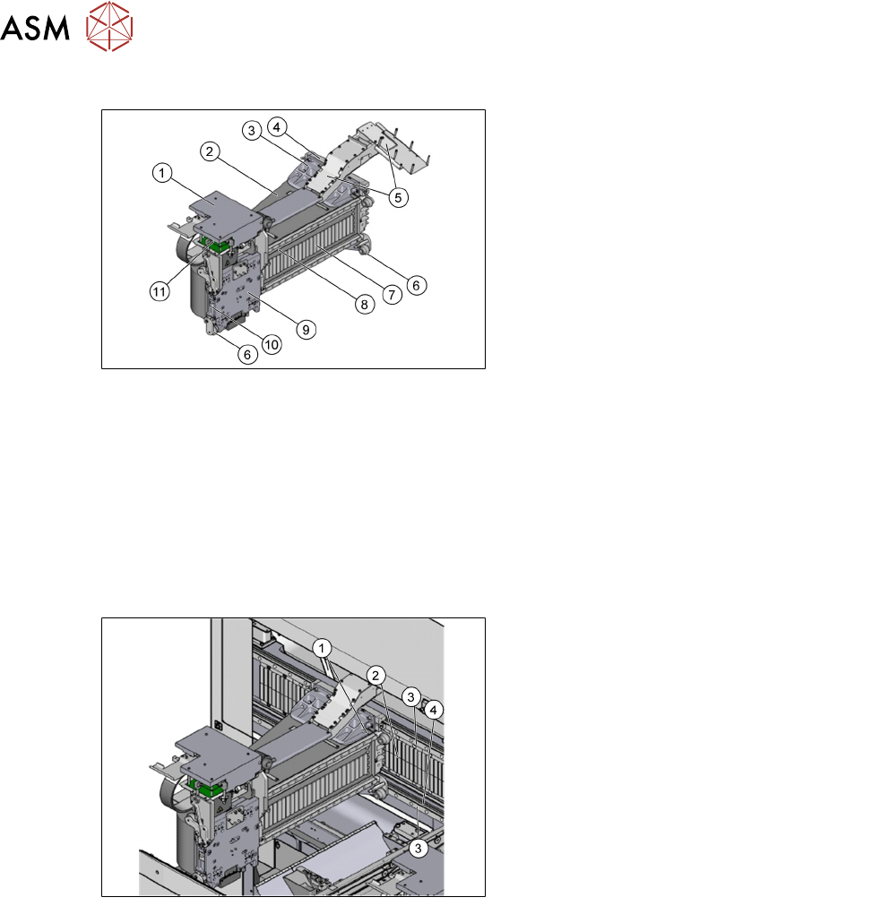
Mechanical Structure of X Axis
1. Board (head interface with Vision board,
below vertical – head adapter board)
2. Gantry arm made of carbon fiber
3. Sensor module for Y Axis*
4. YAxis linear motor (primary)
5. Trailing cable
6. XAxis end position bumper
7. Secondary parts XAxis (magnet)
8. Incremental scale / glass scale*
9. Head mounting plate with integrated
primary part of XAxis linear motor
10. Temperature sensor
11. Sensor module for X Axis (under the head
board)
*Only for TX micron
To improve placement accuracy, the temperature sensors are used to compensate machine
calibration data.
Mechanical Structure of Y Axis
1. Y linear motors (primary part) on the
XAxis gantry
2. Permanent magnet (secondary part of the
YAxis linear motor)
3. Linear guidance system
4. Incremental scale / glass scale*
* Only for TXmicron