00198168-02_Technical_Training_TX-Series_EN.pdf - 第209页
8 Power Supply 8.7 Safety control Technical Training SIPLACE TX-Series 10/2016 209 8.7 Safety control Safety control of output voltages is provided by unit CSB (Contactor based Safety Breaker), which consists of two func…
8 Power Supply
8.6 SMPS diagnostic
208 Technical Training SIPLACE TX-Series 10/2016
8.6 SMPS diagnostic
The diagnostics function in the station software provides easy monitoring of the machine voltage
status.
The following analysis and monitoring options are possible:
●
Monitoring of power pack PS1 and capacitor battery CAP
●
Monitoring of safety states on the CSB
●
Monitoring of intermediate circuit voltages placement heads 160VDC on the FD
●
Monitoring of voltages 42VDC / 28VDC / 24VDC on the FD
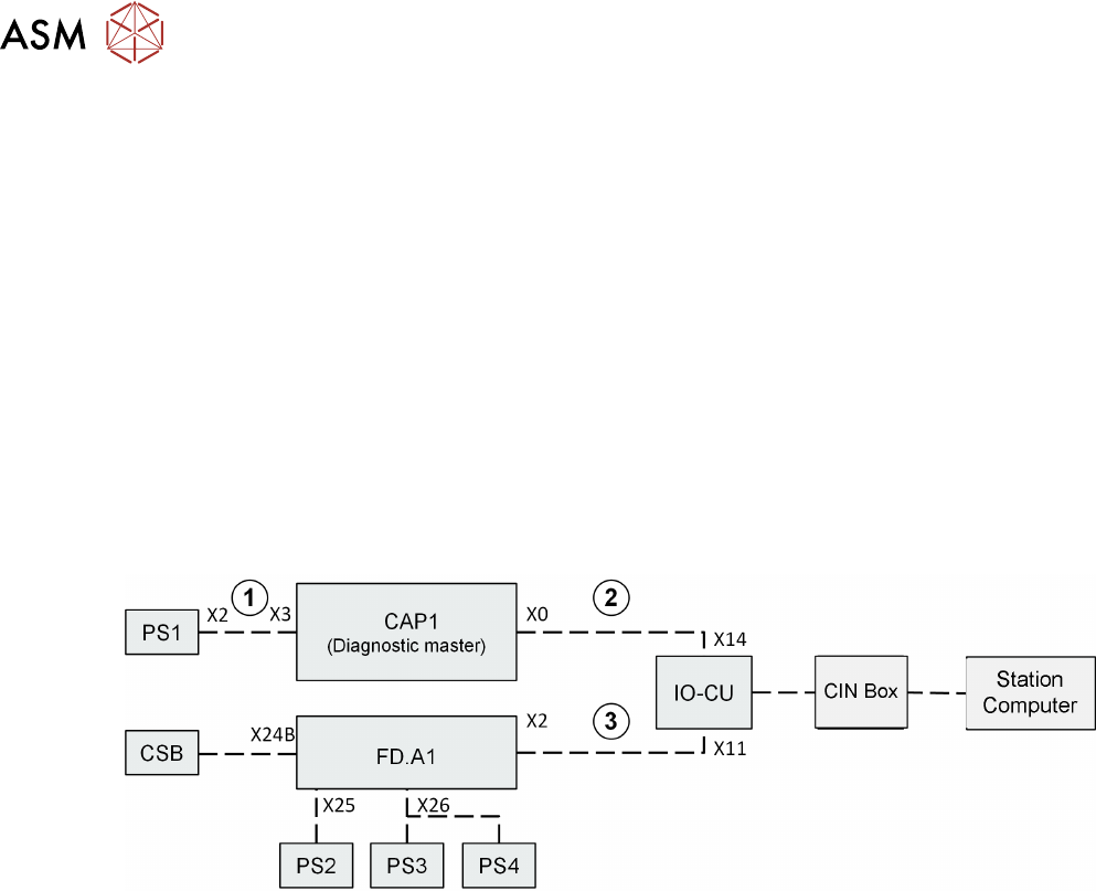
For monitoring the power pack voltages and the fuses on the CAP & FD above, there are also two
additional diagnostics circuits within the SMPS, these two diagnostics circuits are combined on the
IOCU and transferred to the station computer from there.
The connections 1, 2 and 3 are used only to pass on diagnostics data and are therefore essential if
the diagnostics function is to work properly.
●
In order for the diagnostics GUI to function properly, the SMPS cables must be connected
correctly. In case of troubleshooting ensure that all cables are connected correctly. If machine
controller does not receive any diagnostics data for the capacitor battery (e.g. malfunction or
missing cable connection), no diagnostics information will be shown for the FD also!
The Diagnostics Master is a fixed part integrated in the CAP1; it evaluates the information from the
entire PS1-CAP1 assembly as needed for diagnostics.
In addition, the data from the CAP1 capacitor battery (charging status, temperature, backup
storage capacity, working time) are queried by the Diagnostics Master.
FD.A1 collects all diagnostics data for the low voltage monitoring (from PS2/PS3/PS4 / fuses on
FD) and safety logic (from CSB). The diagnostics data is then sent from the FD to the IOCU.
The information about the 160VDC is also queried for the intermediate circuit voltage of the
placement heads. This takes place via the logic on fuses F19 and F20.
8 Power Supply
8.7 Safety control
Technical Training SIPLACE TX-Series 10/2016 209
8.7 Safety control
Safety control of output voltages is provided by unit CSB (Contactor based Safety Breaker), which
consists of two functional units:
1. Circuit Safety Contact Breaker Unit
2. Pre/discharge board –A2 for monitoring and suppressing the load current of the main axes.
The unit provides functionality for:
●
Safety control of output voltages 300/160/42 and 24V
●
Pre-charge external capacitors (300 and 160V lines) within 1s to avoid unauthorized current
loads on connection when switching on output voltages
●
Discharge external capacitors (300 and 160V lines) within 1s to a value below 60V when
switching off output voltages
●
State signaling to Fuse Diagnostic unit located at FD.A1
●
Power enabled signal to MGCU, MHCU and conveyor units
Unit is made of a baseplate that carries contactors and wiring covered by a PCB carrying all
connectors and interfacing.
CAUTION
In event of faulty unit the complete unit needs to be exchanged.
DANGER
Do not open the unit. The unit is completely housed to protect the user from dangerous
voltages. The complete assembly is available as a spare part.
NOTICE
Shuttle safety loop
The safety loop is not a hardware connected to the machine.
The safety loop is controlled by the machine software via CAN bus.
8 Power Supply
8.8 Analysis - Common Error List
210 Technical Training SIPLACE TX-Series 10/2016
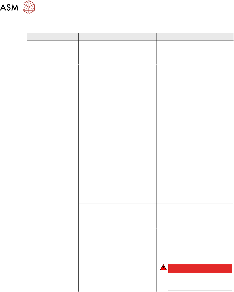
8.8 Analysis - Common Error List
Error Possible Cause Action
No reaction after
START pressed
Duration of pressing and release of
START button
●
Press longer than 200 ms and
shorter than 1500 ms.
START should be accepted on
pushbutton release.
Safety loop closed?
●
Check if both channels of
safety loop show closed
condition
SW_CTRL_ON output of IO
missing?
●
Check: (X29.A6) should be
HIGH if START is pressed
●
Check IO wiring.
●
Check IO output.
●
Check START button wiring.
If output is missing:
●
Replace IO unit
●
Fix START button wiring.
Connection to PCB FD.A1
established?
●
Check connectors X24A and
X24B at FD.A1 and at PCB
CSB
●
Place connectors firm in
position.
Ground connection of PCB CSB
missing?
●
Connect terminal lug to
Ground terminal of CSB.
Supply voltage of CSB missing?
●
Check fuses F12 and F13.
●
Replace fuses F12 and F13, if
needed.
Signal PCC-POWER-OK (X24B.5
at PCB,LED at K5)
If voltage reading > 22V or Power
OK LED of K5 is on→ internal
defect of CSB:
●
Replace unit
24V Measure input voltage
(X24B.3)
If voltage reading > 22V → internal
defect of CSB:
●
Replace unit
Power connectors of CAP and CSB Connectors should be firm in
position.
DANGER!
If you check connectors
mind the dangerous
voltage!
.