00198168-02_Technical_Training_TX-Series_EN.pdf - 第145页
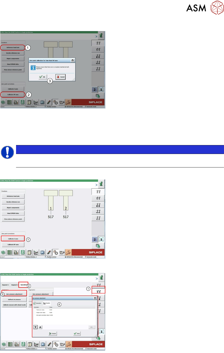
5 Placement Heads 5.3 Twin Head Technical Training SIPLACE TX-Series 10/2016 145 Determining the DP-Axis Zero Point Correction 1. Start the Reference head axis function. 2. Click Calibrate DP axes . The Zero point calibr…
5 Placement Heads
5.3 Twin Head
144 Technical Training SIPLACE TX-Series 10/2016
5.3.7.1 Pre Calibration Procedure
After performing a head exchange or service work on the Twin Head, the following settings are
required for successful calibration of the Twin Head.
1. Entering force Parameters
2. Calibrate Z zero point
3. Calibrate DP zero point
This can be done by selecting the Twin Head under the GUI menu “select sensors and functions of
specific components”.
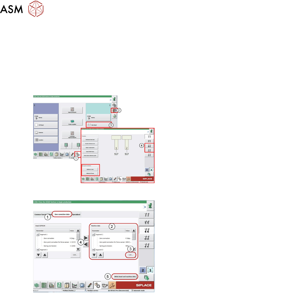
1. Log on as "Service"
2. Click on Sensors and functions menu of
specific components.
3. Click Twin Head.
4. Icon for Z Axis and D Axis Selection
5. Icon for Z and DP Axes Zero point
corrections calibration.
Entering Force Parameters
1. Switch over to the Zero correction data tab.
Current values for both segments 1 and 2.
2. Mark the parameters at Machine data.
3. Click Edit... .
4. Apply the force parameters values from the
Head EEPROM with the arrow buttons (the
values can also be found on the label on the
Twin Head)
5. Click Write head and machine data to save
the values.
5 Placement Heads
5.3 Twin Head
Technical Training SIPLACE TX-Series 10/2016 145
Determining the DP-Axis Zero Point Correction
1. Start the Reference head axis function.
2. Click Calibrate DP axes.
The Zero point calibration dialog is
displayed.
3. Follow the instructions in the window and
confirm with OK.
●
If the calibration is successful, a value will be shown in the "Additional zero point correction"
field. This will be added to the existing value.
●
Repeat the measurement until the Additional zero point correction has a value of zero.
●
Close the window. The value will be automatically saved.
NOTICE
For Twin Heads with Flip Chip camera SST25 for the D Axis zero point correction the
Calibration tool 03123022-xx (2) is required.
Determining the Z Axis Zero Point Correction
1. Click Calibrate Z axes. This will be
determined automatically.
Setting the Pressure Control Valve
The pressure control valve is set to the ambient
pressure. This is important for machines working
at high altitudes.
1. Select Vacuum functions.
2. Click Specialized tab.
3. Click Zero pressure adjustment.
4. You will be issued with a zero point
correction value for the pressure control
valve.
5. The zero point correction value should be 0
+/- 10
5 Placement Heads
5.3 Twin Head
146 Technical Training SIPLACE TX-Series 10/2016
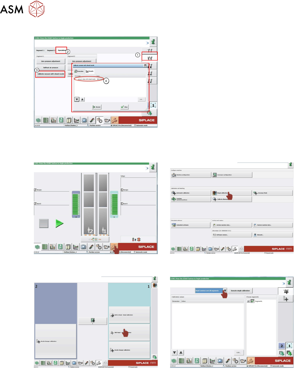
Calibrating the Closed Vacuum
You need a 518 nozzle for this function.
1. Select Vacuum functions
2. Click Specialized tab.
3. Click Calibrate vacuum with closed
nozzle.
4. The gantry moves over the fixed conveyor
rail and moves the Z Axis downwards. When
the nozzle touches the conveyor rail, the
closed nozzle vacuum will be measured. The
vacuum value in mbar will be displayed.
5.3.7.2 Calibration Steps
A 517 nozzle should be in the nozzle changer or on the segments and the calibration tool should
be placed in the pocket on the conveyor rail.
1. Log on as Machine service.
Go to calibration menu.
2. Click on Single calibration.
3. Click on P&P Head - Head calibration. 4. Select Head camera and all segments.