00198168-02_Technical_Training_TX-Series_EN.pdf - 第74页
5 Placement Heads 5.1 CPP Head 74 Technical Training SIPLACE TX-Series 10/2016 Calibration – Procedure 1. Calibration tool 03010565-xx for camera type SSTGigE33 2. Calibration tool 03034148-xx for camera type SST30 3. No…
5 Placement Heads
5.1 CPP Head
Technical Training SIPLACE TX-Series 10/2016 73
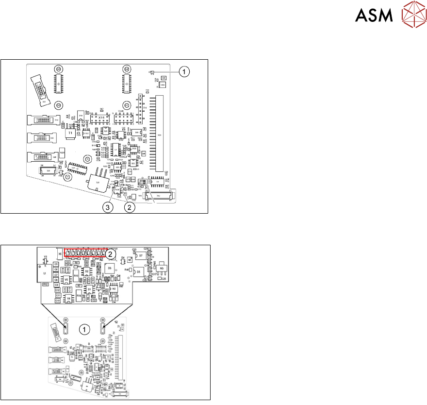
LEDs
1. V14 +24VDC_DP_switched
2. V18 Potential display:
LED on = voltage present
3. V17 Potential display:
LED on = voltage present
5.1.6.2 Addressing the Contactless Energy Transformer
For contactless energy transmission an
additional board is plugged onto the
intermediate distributor 2
1. X31/X32
2. LEDs
V6 Maximum current exceeded
V7 Continuous current too high
V9 KE control switched on (normal opera-
tion ON)
V10 KE transducer error switched OFF
5.1.7 Calibration
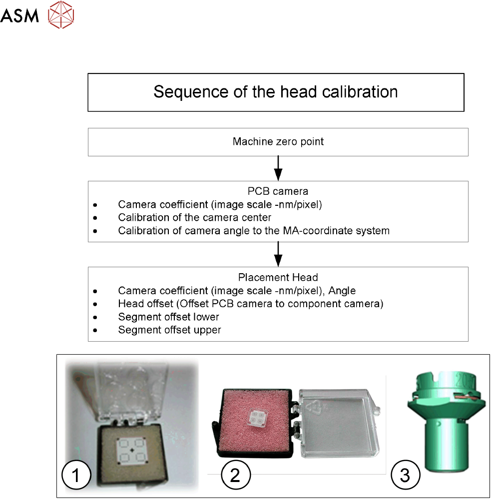
5.1.7.1 Calibration Overview
Calibration - Overview Description
●
Measuring component camera: This determines the relationship of "camera pixel size to
resolution of machine measuring system (X,Y)", "camera center point in X and Y direction"
and the "torsion angle of the CCD sensor".
●
Head offset: the head offset is the distance between the PCB camera and the nozzle
(segment 1). The target is a fixed value, to which an offset value (from the head calibration) is
added.
TX micron only: During the placement cycle the head offset is periodically checked and
calibrated.
●
Segment offset top: the top segment offset involves turning the calibration tool in the
component camera in 0°, 90°, 180° and 270° steps. The value determined is that of the
rotating center of the nozzle tip in relation to the component camera center in the X and Y
direction.
●
Segment offset bottom: the bottom segment offset involves recording and measuring the
calibration tool in the 0°, 90°, 180° and 270° positions. The value determined is that of the
rotating center point of the nozzle tip when the Z Axis is extended in relation to the PCB
camera. Segment 1 forms the reference (X=0, Y=0) to the other segments.
5 Placement Heads
5.1 CPP Head
74 Technical Training SIPLACE TX-Series 10/2016
Calibration – Procedure
1. Calibration tool 03010565-xx for camera type SSTGigE33
2. Calibration tool 03034148-xx for camera type SST30
3. Nozzle 2057 03070280-xx
5 Placement Heads
5.1 CPP Head
Technical Training SIPLACE TX-Series 10/2016 75
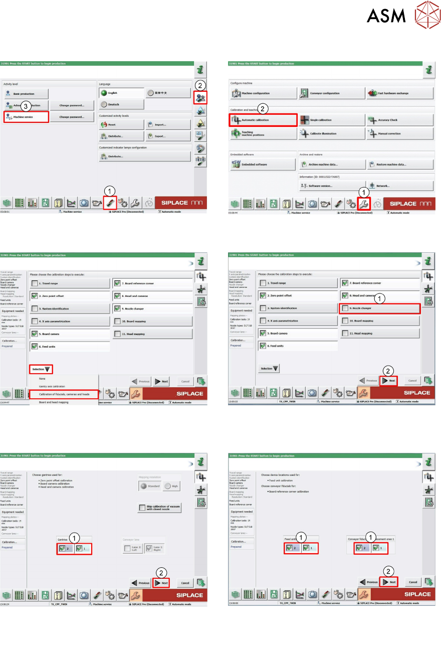
5.1.7.2 Calibration Steps
1. Log on as Machine service (1-3). 2. Click Calibration (1).
Click Automatic calibration (2).
3. Under pull down menu Selection select
Calibration of fiducials, cameras and
heads.
4. Deselect Nozzle changer (1).
Click Next (2).
5. Select required Gantry (1).
Click Next (2).
6. Select required Locations and Place-
ments areas (1).
Click Next (2).