00198168-02_Technical_Training_TX-Series_EN.pdf - 第211页
8 Power Supply 8.8 Analysis - Common Error List Technical Training SIPLACE TX-Series 10/2016 211 Error Possible Cause Action Short reaction of CSB after START pressed ● Check precharge current at 300 V DC link voltage If…
8 Power Supply
8.8 Analysis - Common Error List
210 Technical Training SIPLACE TX-Series 10/2016
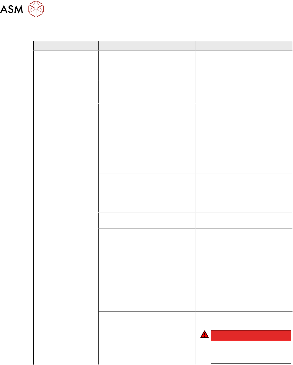
8.8 Analysis - Common Error List
Error Possible Cause Action
No reaction after
START pressed
Duration of pressing and release of
START button
●
Press longer than 200 ms and
shorter than 1500 ms.
START should be accepted on
pushbutton release.
Safety loop closed?
●
Check if both channels of
safety loop show closed
condition
SW_CTRL_ON output of IO
missing?
●
Check: (X29.A6) should be
HIGH if START is pressed
●
Check IO wiring.
●
Check IO output.
●
Check START button wiring.
If output is missing:
●
Replace IO unit
●
Fix START button wiring.
Connection to PCB FD.A1
established?
●
Check connectors X24A and
X24B at FD.A1 and at PCB
CSB
●
Place connectors firm in
position.
Ground connection of PCB CSB
missing?
●
Connect terminal lug to
Ground terminal of CSB.
Supply voltage of CSB missing?
●
Check fuses F12 and F13.
●
Replace fuses F12 and F13, if
needed.
Signal PCC-POWER-OK (X24B.5
at PCB,LED at K5)
If voltage reading > 22V or Power
OK LED of K5 is on→ internal
defect of CSB:
●
Replace unit
24V Measure input voltage
(X24B.3)
If voltage reading > 22V → internal
defect of CSB:
●
Replace unit
Power connectors of CAP and CSB Connectors should be firm in
position.
DANGER!
If you check connectors
mind the dangerous
voltage!
.

8 Power Supply
8.8 Analysis - Common Error List
Technical Training SIPLACE TX-Series 10/2016 211
Error Possible Cause Action
Short reaction of CSB
after START pressed
●
Check precharge current at
300 V DC link voltage
If there is no precharge current
(max 10A):
●
Check GND connection of
CSB
Ground connection of PCB CSB
missing?
●
Connect terminal lug to
Ground terminal of CSB.
If there is GND connection
established:
→ internal defect of CSB;
●
Replace unit
Overload or short circuit at 160 V
DC link output?
●
Remove X24B and try to start.
If Start is working now fix short
circuit conditions at 160V DC link
branch
Overload or short circuit at 300 V
DC link voltage?
●
Remove X21 and X22 and try
to start.
If Start is working now fix short
circuit conditions at 300V DC link
branch
Machine is passing
reference run but stops
at beginning the of
production run
MGCU Error Message: Under-
voltage error at DC link voltage?
●
Check capacitor value of CAP
unit (service screen of dia-
gnostic functions) has to be >
30 mF
If Capacitor value < 30 mF:
●
Replace capacitor unit
●
Check QT40.999 error
messages at service screen
If QT40 error is shown:
●
Replace QT40 unit.
Service screen QT40 unit
●
Check indicator lights at
QT40-999:
Green light (>220V) should be on
during reference run
red light should be on temporary
during gantry acceleration period
DC 42V-S is missing
(Conveyor supply)
Fuse does not work?
Connector X24A (both PCB’s!)
properly connected?
●
Check supply voltage at
FD.A1, F16
Fuse blown or broken?
●
Replace fuse
●
Place connector firm into
place
If error still occurs
→ internal defect of CS:
●
Replace unit

8 Power Supply
8.8 Analysis - Common Error List
212 Technical Training SIPLACE TX-Series 10/2016
Error Possible Cause Action
DC24-S is missing Fuse does not work?
Connector X24A (both PCB’s!)
properly connected?
●
Check supply voltage at
FD.A1, F11
Fuse blown or broken?
●
Replace fuse
●
Place connector firm into
place
If error still occurs
→ internal defect of CSB:
●
Replace unit
POWER-Enabled sig-
nal is missing
Fuse does not work?
Connector X24A (both PCB’s!)
properly connected?
Precharge sequence finished?
DC link voltages are ON)?
●
Check supply voltage at
FD.A1, F11
Fuse blown or broken?
●
Replace fuse
●
Place connector firm into
place
If error still occurs
→ internal defect of CSB:
●
Replace unit
Errors at diagnostic interface:
Error Possible Cause Action
No diagnostic display
(Icon is missing)
Wiring of diagnostic master:
●
Connection between PS1 and
CAP established?
●
Connection between CAP and
IOCU2 established (use
crossover cable!)?
●
Replace wiring.
If there is still no Diagnostic display
available → Diagnostic master at
CAP unit failure:
●
Replace CAP unit
●
QT40 diagnostic supply
voltage available?
●
Internal fuse at CAP unit
blown?
Voltage reading between Pin 1 and
4 of diagnostic connector should be
DC 5V
●
Check QT40 diagnostic supply
voltage.
●
Check internal fuse at CAP
unit.
●
Check voltage reading
between Pins 1 and 4 of
diagnostic connector.
If there is no voltage reading →
CAP unit failure:
●
Replace CAP unit
No fuse diagnostic dis-
play
Wiring to FD.A1:
Connection between FD.A1 and
IOCU2 establisched?
●
Check if FD.A1-X3 is located
firm in its place.
If not:
●
Replace wiring
If there is still no Fuse diagnostics
available:
→ FD.A1 internal error.
●
Replace FD.A1