00198168-02_Technical_Training_TX-Series_EN.pdf - 第138页
5 Placement Heads 5.3 Twin Head 138 Technical Training SIPLACE TX-Series 10/2016 Twin Head - Placement Workflow Standard Placement Detailed 1. Z motor 2. PRV to switch vacuum or air blast 3. Force sensor: measure contact…
5 Placement Heads
5.3 Twin Head
Technical Training SIPLACE TX-Series 10/2016 137
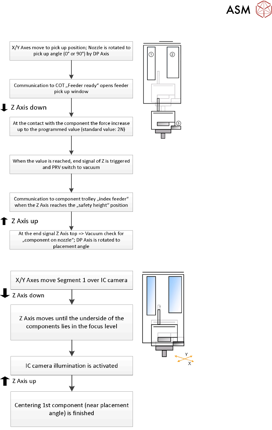
Standard Pick Up Detailed
1. Z Motor
2. PRV to switch vacuum or air blast
3. Force sensor: measure contact force
Twin Head - Optical Centering By IC Camera
5 Placement Heads
5.3 Twin Head
138 Technical Training SIPLACE TX-Series 10/2016
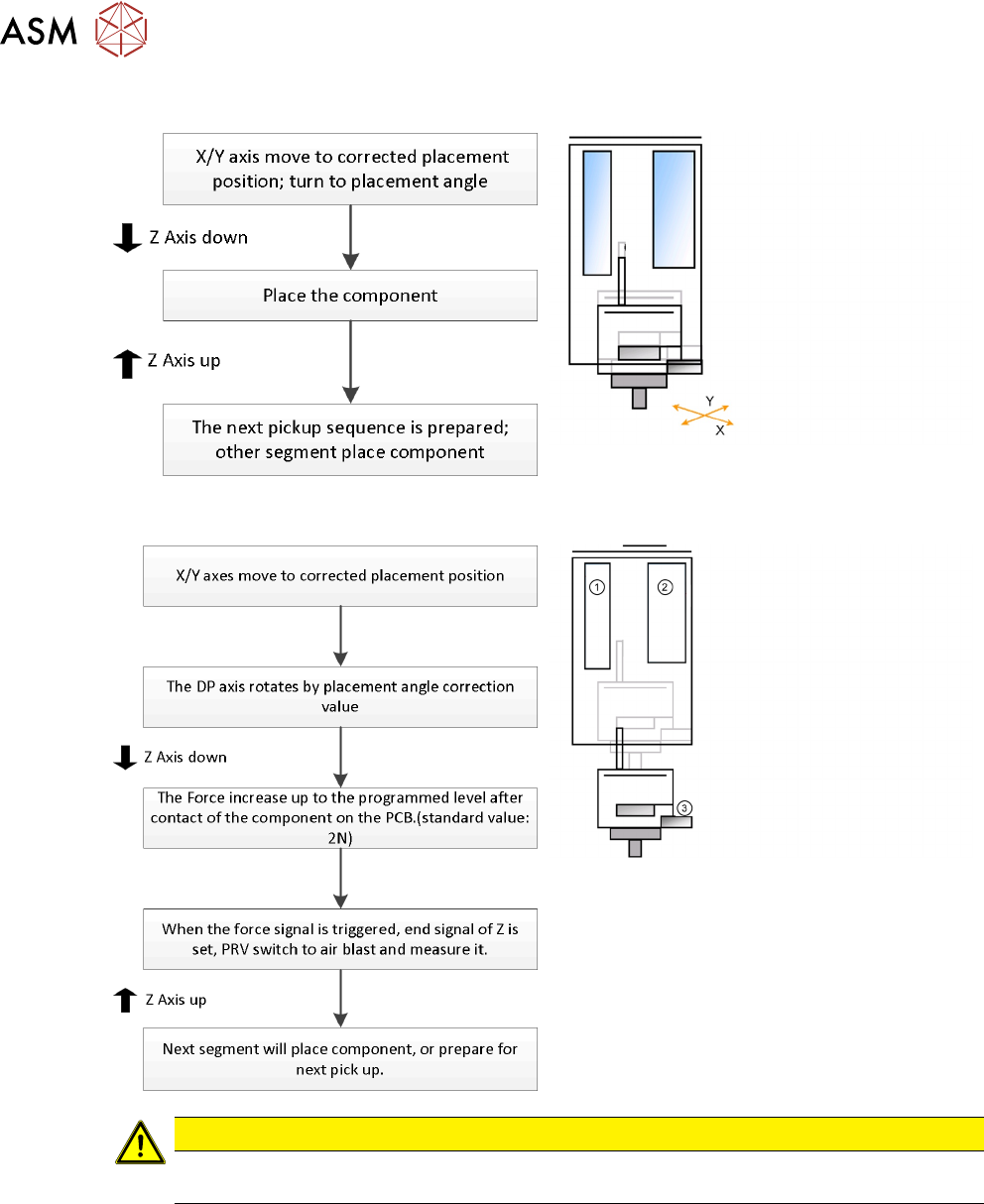
Twin Head - Placement Workflow
Standard Placement Detailed
1. Z motor
2. PRV to switch vacuum or air blast
3. Force sensor: measure contact force
CAUTION
If the air blast pressure is not reached during placement, a vacuum check will be performed
in the Z Axis up position to see whether the component has been placed or not.
Temperature compensation
The temperature sensor is regularly checked and offset value will be calculate and will be used to
increase placement accuracy.
5 Placement Heads
5.3 Twin Head
Technical Training SIPLACE TX-Series 10/2016 139
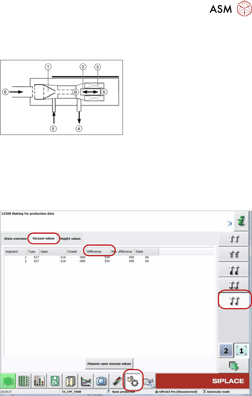
5.3.4 Vacuum System Overview
5.3.4.1 Vacuum System
A - Piston in "open" position
B - Piston in "closed" position
1. Venturi nozzle
2. Plunger (iron core)/ piston
3. Plunger drive (inductor)/ driver circuit
4. Discharged air to silencer
5. Vacuum or air kiss output
6. Compressed air input
PRV – function
●
During pickup the piston is always in the “open” position, in which maximum vacuum is
applied to the nozzle.
●
During placement, the piston is in the "close" position, air kiss is produced and applied to
nozzle for placement.
●
In the placement cycle the time to switch between maximum vacuum (-850 mbar) to
maximum air kiss (+400 mbar) is < 12ms.
5.3.4.2 Station Software Vacuum Check
●
In the case of vacuum errors the vacuum system can be tested using the station software.
●
The differences between open and closed values are measured as reference value for nozzle
check.