00198168-02_Technical_Training_TX-Series_EN.pdf - 第60页
5 Placement Heads 5.1 CPP Head 60 Technical Training SIPLACE TX-Series 10/2016 CPP Head – Placement Positions 1. Optical centering (component camera) 2. Vacuum measurement holding circuit 3. Vacuum measurement placement …
5 Placement Heads
5.1 CPP Head
Technical Training SIPLACE TX-Series 10/2016 59
5.1.3 Placement Process
5.1.3.1 Placement Positions
CPP Head - Placement Modes
Placement mode is optimize by SIPLACE Pro depending on size of component and configured
camera type.
Note : TX micron machines only support C&P mode.
C&P mode: High speed placement with small component
1. Standard Collect and Place Mode, max.
component size is dependent on the
camera configuration.
2. Components size up to 32 x 32mm, but
they have to be centered with a stationary
camera.
Mixed mode: High efficient placement with different size of component
1. C&P mode, but some components are
centered with stationary camera.
2. When last component is picked up, head
moves to stationary camera for centering,
and then place this component first without
turning.
PP mode: High capacity for large component placement
●
The Pick and Place mode is the same as
the IC and Twin head.
●
Pick up one component with one segment,
move to the stationary camera and center
the component and then place it.
5 Placement Heads
5.1 CPP Head
60 Technical Training SIPLACE TX-Series 10/2016
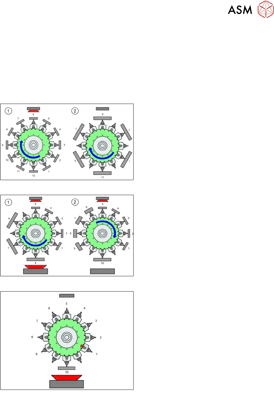
CPP Head – Placement Positions
1. Optical centering (component camera)
2. Vacuum measurement holding circuit
3. Vacuum measurement placement circuit
4. Pickup/placement station and reject
position
5. Position of component sensor
6. Direction of processing in C&P mode
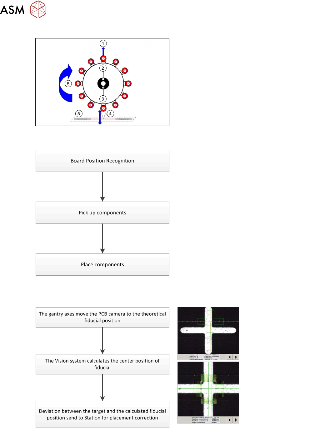
5.1.3.2 Placement Workflow
●
The PCB camera centers the fiducial after
clamping to determine the exact position of
the board.
●
Max. 12 components will be picked up.
Components are then centered under the
component camera.
●
Place components on PCB according to
the program.
Board Position Recognition
5 Placement Heads
5.1 CPP Head
Technical Training SIPLACE TX-Series 10/2016 61
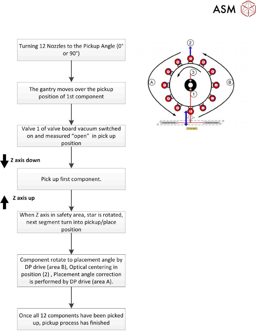
Pick Up Workflow
A Placement angle correction after optical
centering
B Rotate component into placement angle
1. Vacuum measurement pick up/ place
circuit
2. Optical centering (SIPLACE Vision)
3. Vacuum measurement holding circuit
If a component fails the optical centering (identity error), then this component remains on the
nozzle. After all other components have been placed, the failed component will go to the reject
cycle.