00198168-02_Technical_Training_TX-Series_EN.pdf - 第61页
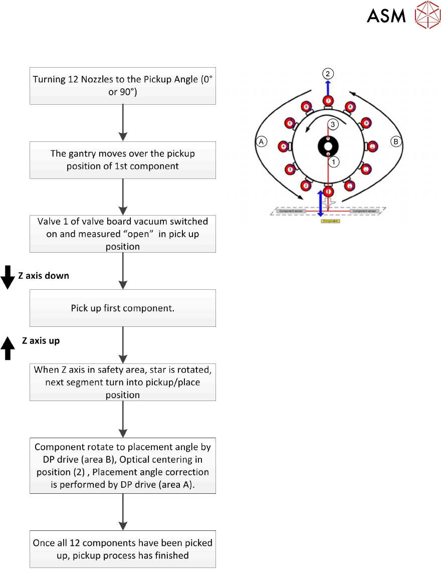
5 Placement Heads 5.1 CPP Head Technical Training SIPLACE TX-Series 10/2016 61 Pick Up Workflow A Placement angle correction after optical centering B Rotate component into placement angle 1. Vacuum measurement pick up/ …
5 Placement Heads
5.1 CPP Head
60 Technical Training SIPLACE TX-Series 10/2016
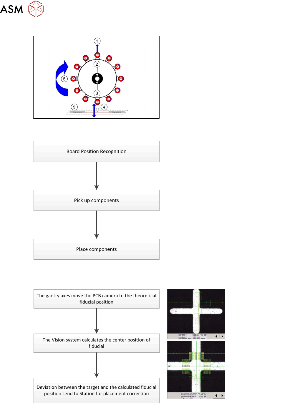
CPP Head – Placement Positions
1. Optical centering (component camera)
2. Vacuum measurement holding circuit
3. Vacuum measurement placement circuit
4. Pickup/placement station and reject
position
5. Position of component sensor
6. Direction of processing in C&P mode
5.1.3.2 Placement Workflow
●
The PCB camera centers the fiducial after
clamping to determine the exact position of
the board.
●
Max. 12 components will be picked up.
Components are then centered under the
component camera.
●
Place components on PCB according to
the program.
Board Position Recognition
5 Placement Heads
5.1 CPP Head
Technical Training SIPLACE TX-Series 10/2016 61
Pick Up Workflow
A Placement angle correction after optical
centering
B Rotate component into placement angle
1. Vacuum measurement pick up/ place
circuit
2. Optical centering (SIPLACE Vision)
3. Vacuum measurement holding circuit
If a component fails the optical centering (identity error), then this component remains on the
nozzle. After all other components have been placed, the failed component will go to the reject
cycle.
5 Placement Heads
5.1 CPP Head
62 Technical Training SIPLACE TX-Series 10/2016
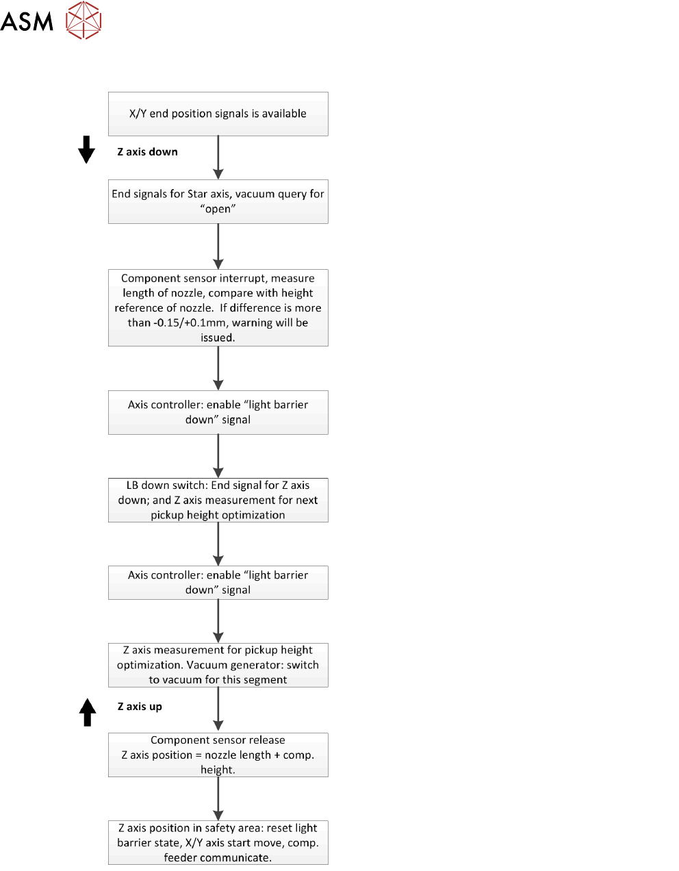
Pick Up Workflow detailed
Holding circuit of each segment is switched on via the valve board, just before pickup is performed.
Since the travel paths for each axis can be calculated, the next action (e.g. starting the Z Axis) is
started via position flags.
For example: The Z Axis to start moving down 10ms earlier before end signals from Star Axis.