00198168-02_Technical_Training_TX-Series_EN.pdf - 第136页
5 Placement Heads 5.3 Twin Head 136 Technical Training SIPLACE TX-Series 10/2016 Board Position Recognition Pick Up Workflow 1. Module 1 (Segment 1) 2. Module 2 (Segment 2)
5 Placement Heads
5.3 Twin Head
Technical Training SIPLACE TX-Series 10/2016 135
Reference Run: Vacuum Value Explanation
After the CAN bus processor for the vacuum/air blast distributor has booted, the vacuum / air blast
distributor is initialized. This means that vacuum/air blast generator is adjusted to ensure that
neither vacuum nor air blast is generated at the nozzle.
The gantry axes move the Twin Head to the reject position.
●
Over the reject box the vacuum / air blast generator switches to air blast to reject components
and check the air blast.
●
The vacuum/air blast generator now switches over to vacuum and the open vacuum at the
segments is measured*.
●
After measurement, the pressure is adjusted back to 0 bar
●
The vacuum reference run has now been completed for the Twin Head.
*The closed vacuum value for the Twin segments relates to the calibration value.
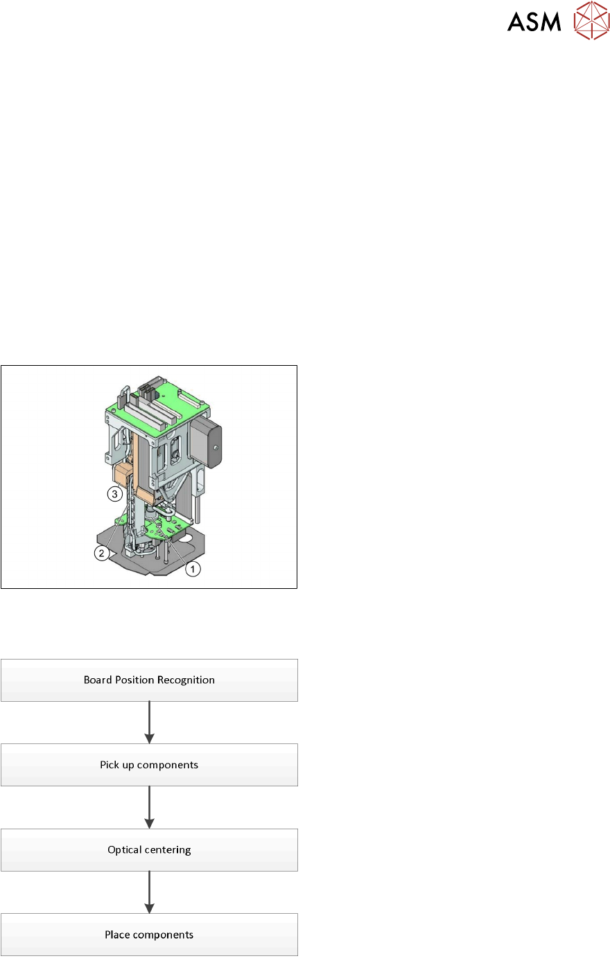
5.3.3 Placement Process
Twin Head - Working Position
1. DP Axis
2. Z Axis drive
3. Incremental distance measuring system for
the Z Axis
All following procedures are for both Segments.
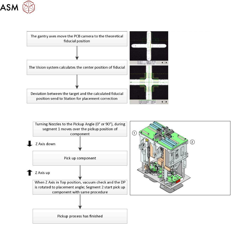
Twin Head - Placement Workflow
●
PCB camera centers fiducials after PCB is
clamped to determine the exact position of
the board in the machine.
●
Max. 2 components will be pick up from
feeder (1-per segment).
●
These components will be centered by
IC-camera and prepared for placement.
●
Place components on PCB.
5 Placement Heads
5.3 Twin Head
136 Technical Training SIPLACE TX-Series 10/2016
Board Position Recognition
Pick Up Workflow
1. Module 1 (Segment 1)
2. Module 2 (Segment 2)
5 Placement Heads
5.3 Twin Head
Technical Training SIPLACE TX-Series 10/2016 137
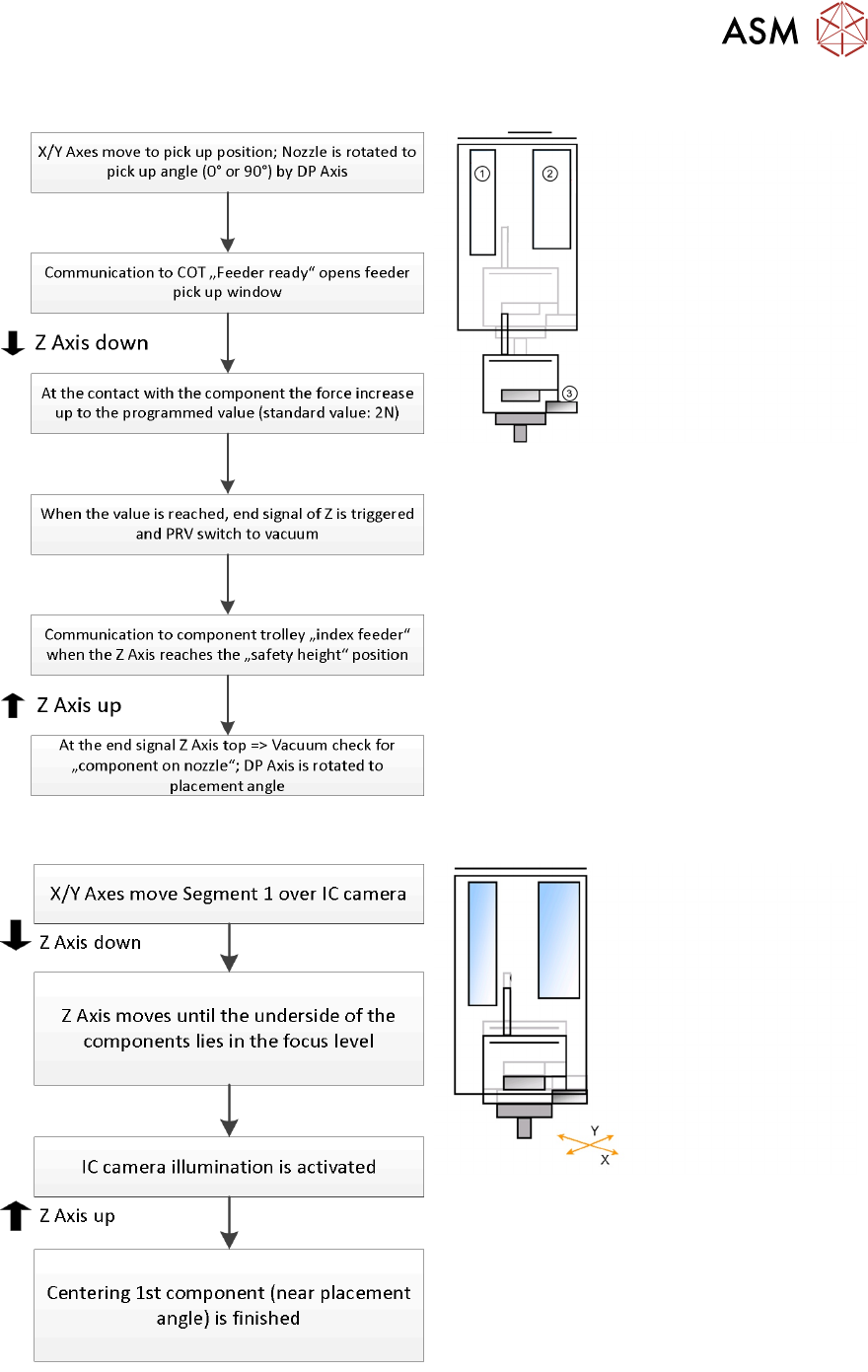
Standard Pick Up Detailed
1. Z Motor
2. PRV to switch vacuum or air blast
3. Force sensor: measure contact force
Twin Head - Optical Centering By IC Camera