00198168-02_Technical_Training_TX-Series_EN.pdf - 第96页
5 Placement Heads 5.2 C&P20 P/M2 Head 96 Technical Training SIPLACE TX-Series 10/2016 5.2.2.9 Pressure Control Valve (PRV) 1. Energy and data supply 2. Compressed air connection 3. Vacuum/air kiss for pickup/placemen…
5 Placement Heads
5.2 C&P20 P/M2 Head
Technical Training SIPLACE TX-Series 10/2016 95
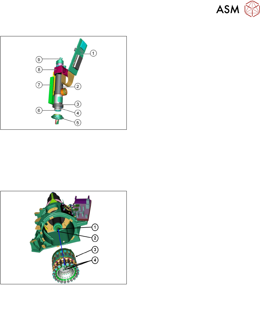
5.2.2.7 DP Drive
1. Control board for DP Motor
2. Motor
3. New non-transparent switching disk, can’t
be changed anymore
4. Nozzle interface
5. New nozzle type 4xxx with new nozzle
interface
6. Filter disc
7. Linear guide
8. Measurement system *
9. Vacuum / Air Kiss connection
*C&P20 M2: New DP drive with more accuracy
●
The DP drive is responsible for turning the nozzles into the correct pickup position and the
component into the correct placement angle.
●
Vacuum and air blast to the nozzle are provided via the motor shaft of the DP Axis.
●
The complete DP drive with linear guidance can be replaced during service work.
5.2.2.8 Star
1. Motor shaft
2. Grinding disc
3. Star assembly
4. Screws mounting the star unit to the motor
shaft
●
The star consists of the star frame on which all 20 DP drives are mounted, the motherboard
and the collector ring.
●
This complete unit is fixed to the motor shaft with three screws.
Note: The Star is not a spare part.
5 Placement Heads
5.2 C&P20 P/M2 Head
96 Technical Training SIPLACE TX-Series 10/2016
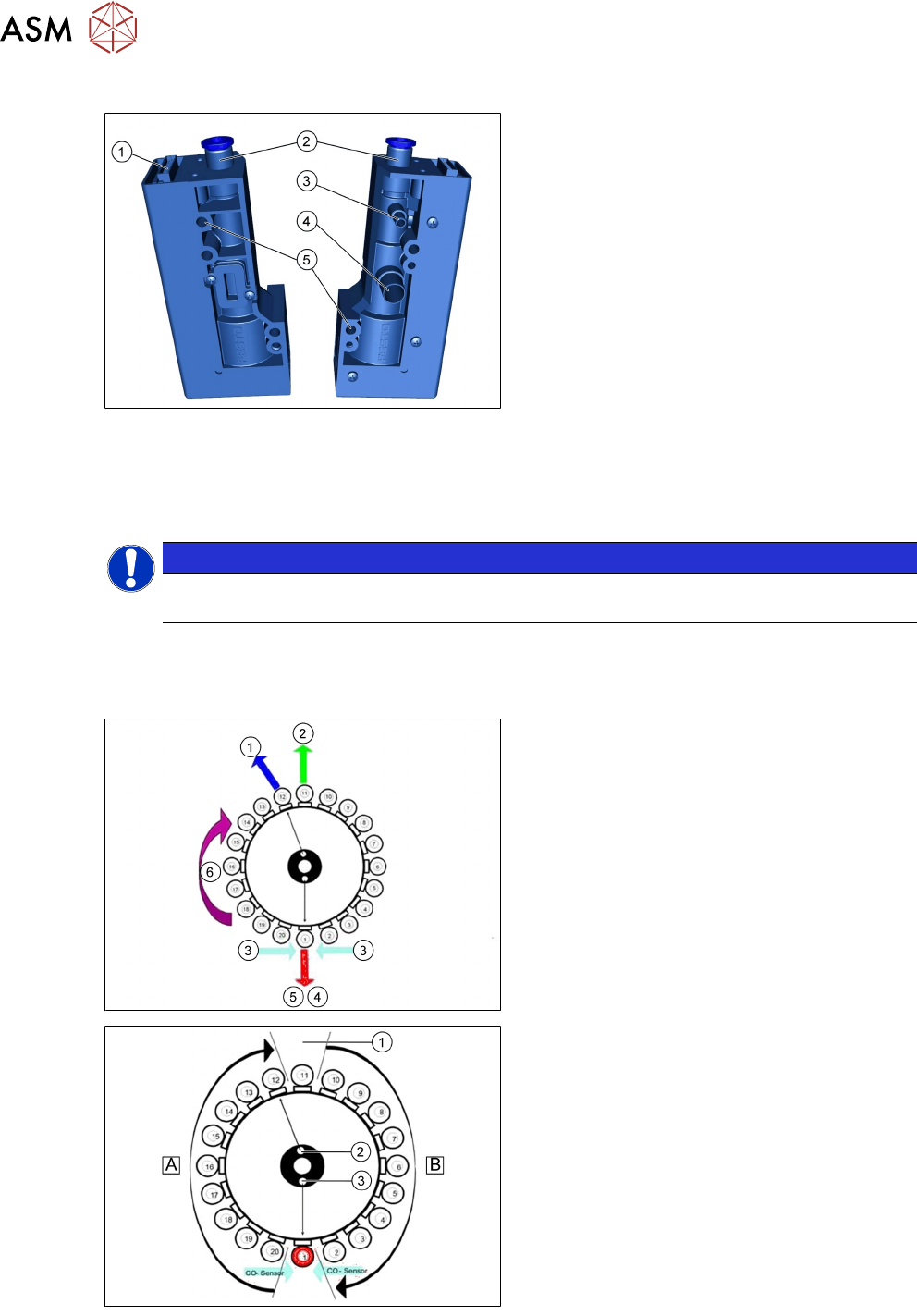
5.2.2.9 Pressure Control Valve (PRV)
1. Energy and data supply
2. Compressed air connection
3. Vacuum/air kiss for pickup/placement
circuit
4. Discharged air for cooling the X linear
motor
5. Mounting for pressure control valve
●
The PRV supplies the pickup/placement circuit with vacuum during the pickup process and
switches over to air kiss during placement.
●
The valve can be replaced during service work.
●
Sensitivity against dirt and dust is reduced.
NOTICE
The PRV introduced with the C&P20 P is not to be cleaned. Otherwise the built in
protection membrane can be damaged.
5.2.3 Placement Process
5.2.3.1 Placement Positions
1. Vacuum measurement holding circuit
2. Optical centering (component camera)
3. Position of component sensor
4. Vacuum measurement placement circuit
5. Pickup/ placement position and reject
position
6. Direction of processing in C&P mode
A - Rotate component into placement angle
B - Placement angle correction after optical
centering
1. Optical centering (SIPLACE Vision)
2. Vacuum measurement holding circuit
3. Vacuum measurement pickup/ place circuit
5 Placement Heads
5.2 C&P20 P/M2 Head
Technical Training SIPLACE TX-Series 10/2016 97
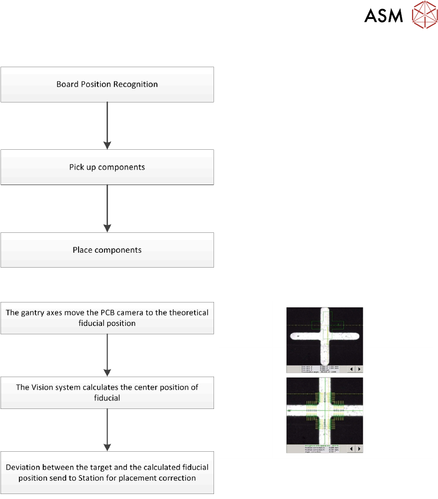
5.2.3.2 Placement Workflow
●
Use PCB camera to center fiducial after
clamping to determine the exact position of
the board.
●
Max. 20 components will be picked up.
Components are then centered under the
component camera.
●
Place components on PCB according to
the program.
Board Position Recognition