00198168-02_Technical_Training_TX-Series_EN.pdf - 第21页
2 Machine Basic Overview 2.4 Machine Configuration Technical Training SIPLACE TX-Series 10/2016 21 2.4 Machine Configuration TX 1 Machine Configuration One gantry with 1 head type: ● CPP Head – camera type 30 and station…
2 Machine Basic Overview
2.3 Overview main components
20 Technical Training SIPLACE TX-Series 10/2016
Other options
Reject plate Components can be rejected onto a reject tray
sized 110mm x 70mm.
Input conveyor extension Needed for barcode reader
Output conveyor extension Needed for JTF-ML
Interior illumination For service work
Reconfiguration kit for LDU-X
Second light barrier in conveyor placement area For running convoy mode
PCB barcode reader On input conveyor extension
GlueFeeder Glue application with maximum precision
TX micron configurations
TX micron is available in the following configurations:
TX2i micron and TX2 micron (20 / 25μm) or TX2i micron 15μm with a license.
TX micron 20 / 25µm (standard) TX micron 15µm
X/Y Glass scale / encoder X/Y Glass scale / encoder
Sensor module X/Y Sensor module X/Y
X-fiducial bar X-fiducial bar
C&P20 M2 / CPP M C&P20 M2 / CPP M
Option vacuum tooling Vacuum tooling preparation transport TX
(stiftness lifting table)
Stiftness lifting table Basic pack vacuum tooling
License TX micron 15µ 3Sigma machine
connection
Customer specific vacuum tooling with
Y-fiducial bar
Optional:
Vacuum tooling TX micron (to measure the
accuracy with the new ACT board)
For further options and details refer to the User manual.
2 Machine Basic Overview
2.4 Machine Configuration
Technical Training SIPLACE TX-Series 10/2016 21
2.4 Machine Configuration
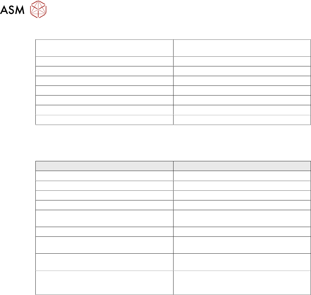
TX 1 Machine Configuration
One gantry with 1 head type:
●
CPP Head – camera type 30 and
stationary camera type 33 on location 1.
●
C&P20 P Head camera type 23 or 41
●
Twin Head stationary camera type 33 or
25
●
JTF-ML (only Location1)
●
Reject Tray (only Location1)
Table position:
●
Location 1: Outer
●
Location 2: Inner
Gantry upgrade to TX2 possible
Feeder Count With C&P20 P With CPP With Twin Head
Location 1 38 40 40*
Location 1 with JTF ML - 28 28
Location 2 38 40 40*
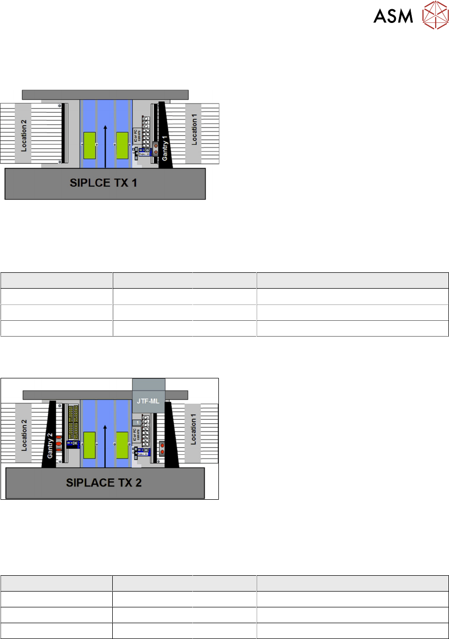
TX 2 Machine Configuration
Two gantries with same or different head
types possible:
●
C&P20 P / C&P20 P camera type 23 or 41
●
TH stationary camera type 25 or 33
/ CPP camera type 30
●
CPP / CPP camera type 30
●
CPP** / CPP** camera type 30 and
stationary camera type 33 on location 1
●
JTF-ML (only Location1)
●
Reject Tray (only Location1)
Table Position:
●
Location 1: Outer
●
Location 2: Inner
Feeder Count With C&P20 P With CPP With Twin Head
Location 1 38 40 40*
Location 1 with JTF ML - 28 28
Location 2 38 40 Not Applicable
*The right segment cannot reach 3 tracks on the left side of the table; the left segment cannot
reach 3 tracks on the right side of the table.
**The CPP Head has a low and a high installation position (with low position a stationary
component camera is not possible).
2 Machine Basic Overview
2.4 Machine Configuration
22 Technical Training SIPLACE TX-Series 10/2016
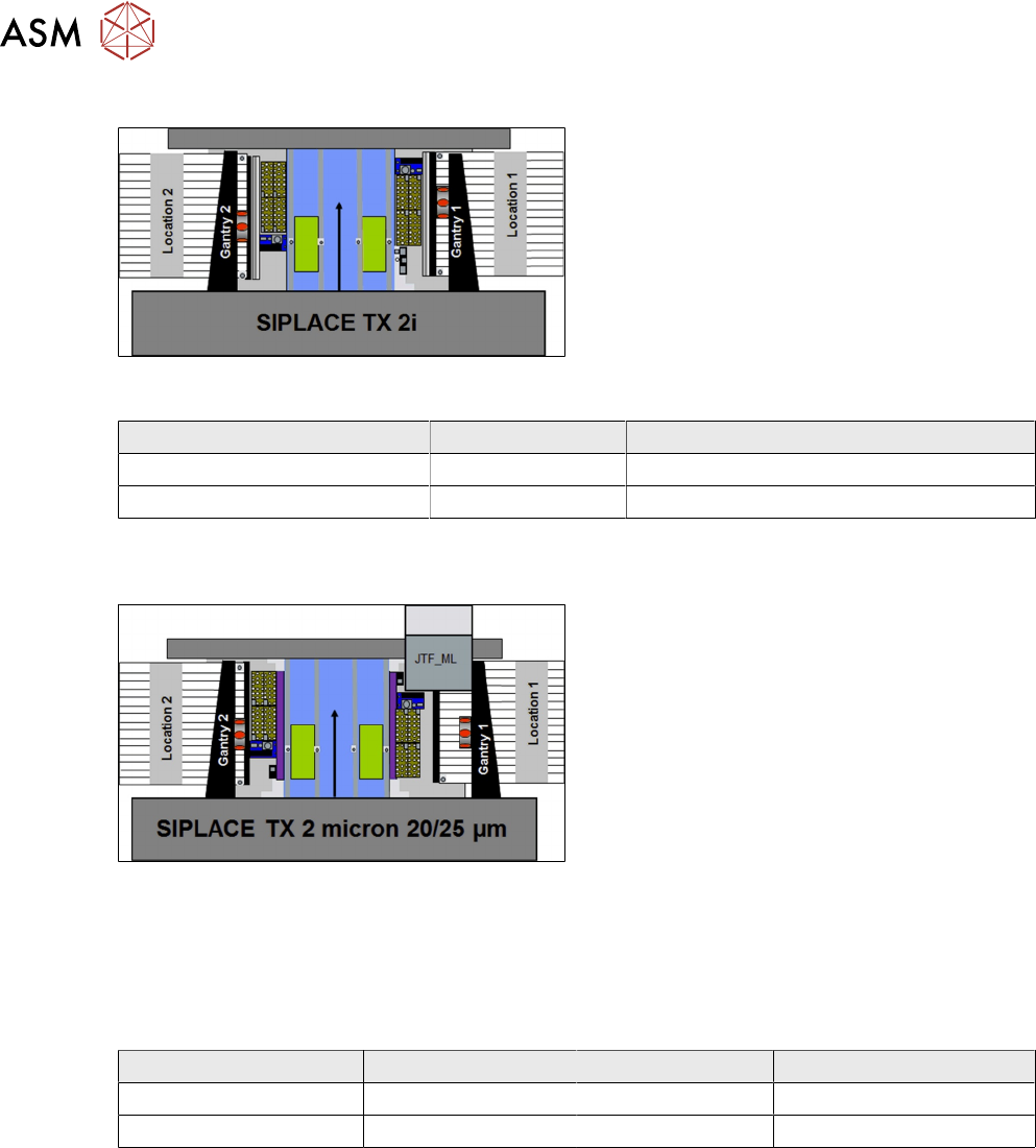
TX 2i Machine Configuration
Two gantries with same head types:
●
C&P20 P / C&P20 P camera type 23 or 41
●
CPP / CPP camera type 30
Table Position:
●
Location 1: Inner
●
Location 2: Inner
Other:
●
No stationary camera
●
No Tray units (JTF)
Feeder Count With C&P20 P With CPP
Location 1 38 40
Location 2 38 40
TX 2 micron 20/25 µm Machine Configuration
Two gantries with same or different head
types possible:
●
C&P20 M2 / C&P20 M2 camera type 41
●
CPP M_H_L / CPP M_H_L camera type
45
●
X-fiducial bar
●
No stationary cameras
●
JTF-ML on Loc.1
Note:
When JTF is used the CPP head must be
mounted in the high position.
Table Position:
EOL application
●
Location 1: Outer
●
Location 2: Inner
Feeder Count With C&P20 M2 With CPP M CPP M with JTF_ML
Location 1 38 40 28
Location 2 38 40 40